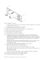


b.
Push the drive drawer all the way in until the latch fully engages.
7.
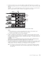
Install the cable chains on the rear of the drive drawer by completing the following steps:
a.
Remove the left fan assembly. See “Replacing a fan assembly” on page 120 for the steps to
remove a fan assembly.
b.
Connect the left cable chain mounting bracket to the drive drawer. Use a flashlight, if necessary,
so that you can see the connector on the mounting bracket connect to the midplane connector.
c.
Connect the left cable chain mounting bracket to the midplane.
d.
Reinstall the left fan assembly. Wait until the fan speed slows down before proceeding to ensure
that the left fan assembly is operating correctly before removing the right fan assembly. See
“Replacing a fan assembly” on page 120 for the steps to install a fan assembly.
e.
Remove the right fan assembly. See “Replacing a fan assembly” on page 120 for the steps to
remove a fan assembly.
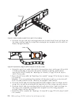
f.
Use the handle to pull the right fan assembly out of the storage expansion enclosure.
g.
Connect the right cable chain mounting bracket to the drive drawer.
h.
Connect the right cable chain mounting bracket to the midplane. Use a flashlight, if necessary, so
that you can see the connector on the mounting bracket connect to the midplane connector.
i.
Reinstall the right fan assembly.
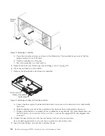
8.
Install the disk drives in the new drive drawer FRU by completing the following steps:
a.
Open the drive drawer by pulling the handles on the drive drawer towards you until the drive
drawer stops.
b.
Install the drives you that you removed previously in the drive drawer, one disk drive at a time.
Wait at least 90 seconds or until each drive is recognized in the DS Storage Manager Physical
View before inserting the next drive. If you do not wait until the drive is recognized by the DS
Storage Manager, one or more drives will be marked as failed/bypassed or incompatible. If this
occurs, you must remove the failed/bypassed drive, reinsert it, and wait at least 90 seconds or
until it is recognized by the DS Storage Manager. See “Installing hot-swap hard disk drives” on
page 101 for the steps to install the drives.
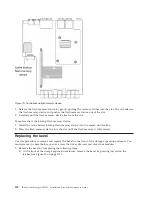
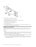
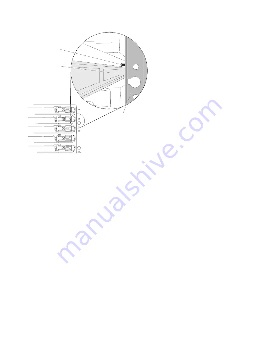
Drawer
guide
lock-out
tumbler
Enclosure
frame
Figure 87. Lock-out tumbler located above the drawer guide
126
IBM System Storage DCS3700: Installation, User, and Maintenance Guide
Содержание DCS3700
Страница 1: ...IBM System Storage DCS3700 Installation User and Maintenance Guide...
Страница 2: ......
Страница 3: ...IBM System Storage DCS3700 Installation User and Maintenance Guide...
Страница 8: ...vi IBM System Storage DCS3700 Installation User and Maintenance Guide...
Страница 12: ...x IBM System Storage DCS3700 Installation User and Maintenance Guide...
Страница 18: ...xvi IBM System Storage DCS3700 Installation User and Maintenance Guide...
Страница 22: ...xx IBM System Storage DCS3700 Installation User and Maintenance Guide...
Страница 62: ...40 IBM System Storage DCS3700 Installation User and Maintenance Guide...
Страница 75: ...Figure 34 Single Expansion Enclosures Chapter 3 Cabling the DCS3700 53...
Страница 76: ...Figure 35 Dual Expansion Enclosures 54 IBM System Storage DCS3700 Installation User and Maintenance Guide...
Страница 88: ...66 IBM System Storage DCS3700 Installation User and Maintenance Guide...
Страница 150: ...128 IBM System Storage DCS3700 Installation User and Maintenance Guide...
Страница 168: ...146 IBM System Storage DCS3700 Installation User and Maintenance Guide...
Страница 178: ...156 IBM System Storage DCS3700 Installation User and Maintenance Guide...
Страница 180: ...158 IBM System Storage DCS3700 Installation User and Maintenance Guide...
Страница 188: ...166 IBM System Storage DCS3700 Installation User and Maintenance Guide...
Страница 198: ...176 IBM System Storage DCS3700 Installation User and Maintenance Guide...
Страница 201: ......
Страница 202: ...Part Number 90Y8588 Printed in USA 1P P N 90Y8588...


