


System-board
LEDs
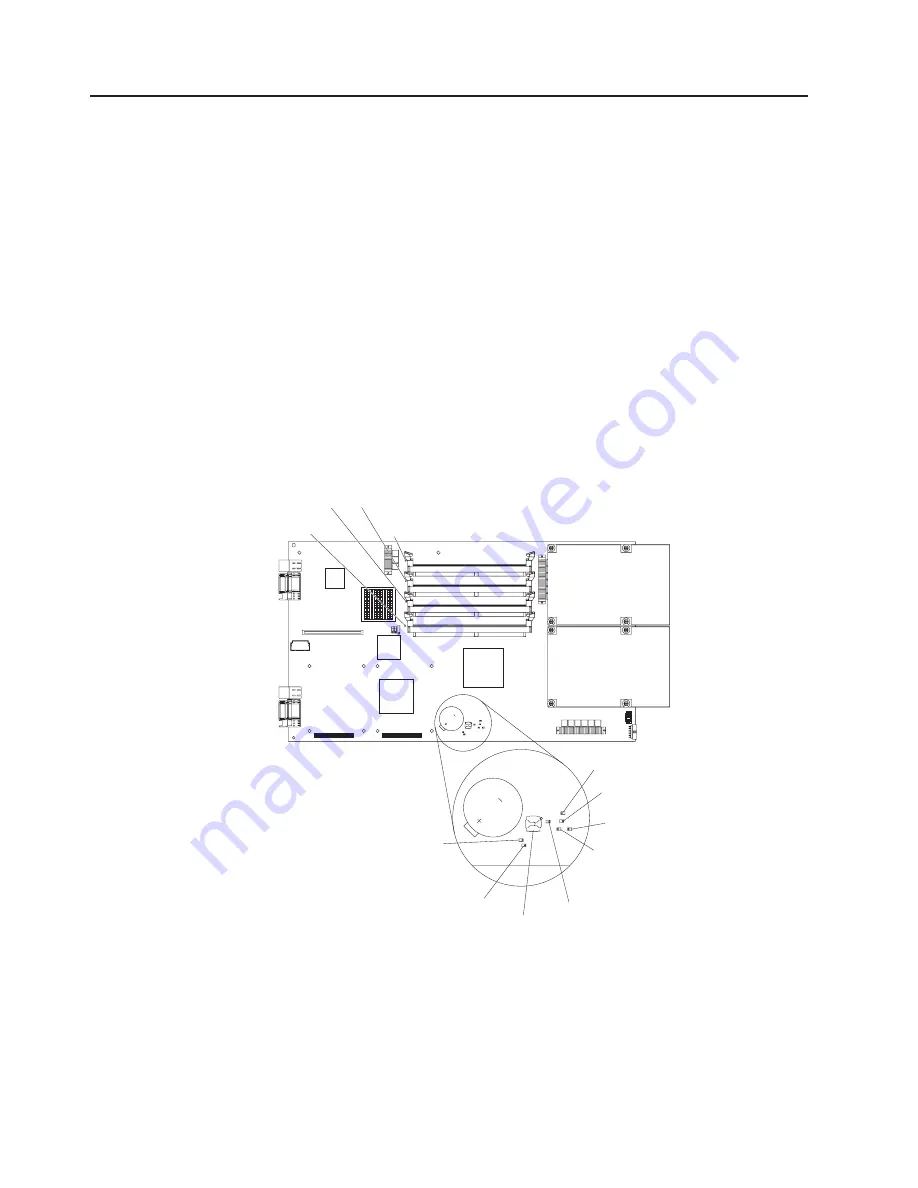
The
following
illustration
shows
the
location
of
the
LEDs
on
the
system
board.
You
might
need
to
refer
to
this
illustration
when
solving
problems
with
the
blade
server.
You
must
remove
the
blade
server
from
the
BladeCenter
unit,
open
the
cover,
and
press
the
light
path
diagnostics
button
(SW1)
to
light
any
error
LEDs
that
were
turned
on
during
processing.
Notes:
v
Power
is
available
to
light
the
light
path
diagnostics
LEDs
for
a
short
period
of
time
after
the
blade
server
is
removed
from
the
BladeCenter
unit.
During
that
period
of
time,
you
can
light
the
light
path
diagnostics
LEDs
for
a
maximum
of
25
seconds
(or
less,
depending
on
the
number
of
LEDs
that
are
lit
and
the
length
of
time
the
blade
server
is
removed
from
the
BladeCenter
unit)
by
pressing
the
light
path
diagnostics
button
(SW1).
v
Error
LED
CR29
is
not
used.
v
For
the
locations
of
the
corresponding
DIMM
sockets
and
microprocessor
connectors
on
the
system
board,
see
the
illustration
in
“System-board
internal
and
option
connectors”
on
page
15.
DIMM 1 error
LED (CR40)
DIMM 3 error
LED (CR46)
DIMM 2 error
LED (CR45)
DIMM 4 error
LED (CR53)
Microprocessor 1
error LED (CR58)
Microprocessor 0
error LED (CR19)
Temperature
error LED (CR16)
NMI error
LED (CR17)
System board
error LED (CR20)
Service processor
error LED (CR27)
Light Path Diagnostics
(SW1)
Reserved (CR29)
16
BladeCenter
JS20
Type
8842:
Installation
and
User’s
Guide
Содержание BladeCenter JS20
Страница 3: ...BladeCenter JS20 Type 8842 Installation and User s Guide ...
Страница 46: ...34 BladeCenter JS20 Type 8842 Installation and User s Guide ...
Страница 120: ...108 BladeCenter JS20 Type 8842 Installation and User s Guide ...
Страница 131: ......
Страница 132: ... Part Number 31R1749 Printed in USA 1P P N 31R1749 ...


