12
Installing external options
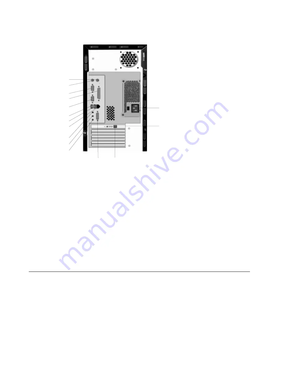
The following illustration shows the location of the connectors on the rear of the microtower
model.
Note:
The connectors on the rear of the computer have color-coded icons. Icons will help you
to determine where to connect the proper cables on your computer.
1 Power connector
9 USB connector
2 Speaker out connector
10 USB connector
3 S/PDIF connector (some models only)
11 Monitor connector
4 Game Port (some models only)
12 Parallel connector
5 Microphone connector
13 Serial connector
6 Audio line-in connector
14 Keyboard connector
7 Audio line-out connector
15 Mouse connector
8 LAN connector
Connector
Description
Mouse connector
Used to attach a mouse, trackball, or other pointing device that uses a mouse
connector.
Keyboard connector
Used to attach a keyboard that uses a keyboard connector.
USB connectors
Used to attach a device that requires a Universal Serial Bus (USB) connection, such as
a USB scanner or USB printer. If you have more than four USB devices, you can
purchase a USB hub, which you can use to connect additional USB devices.
Serial connectors
Used to attach an external modem, serial printer, or other device that uses a 9-pin
serial connector.
Parallel connector
Used to attach a parallel printer, parallel scanner, or any other device that requires a
25-pin parallel connection.
1
2
3
4
5
6
7
8
9
10
11
12
13
14
15
Содержание A20i 2255
Страница 1: ......
Страница 4: ...iv Contents...
Страница 10: ...x About this book...
Страница 18: ...8 Overview...
Страница 24: ...14 Installing external options...
Страница 34: ...24 Installing internal options desktop model...
Страница 46: ...36 Installing internal options microtower model...
Страница 52: ...42 Updating the computer configuration...
Страница 56: ...46 Updating System Programs...
Страница 62: ...52 Notices and trademarks...
Страница 65: ......
Страница 66: ...Part Number 22P0801...


