background image

6.1

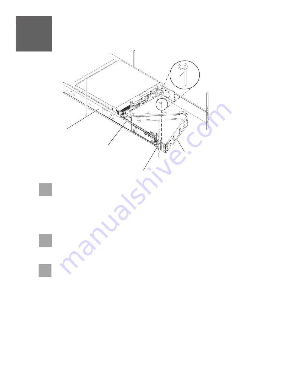
Locate the cable-management arm

and the two pins .

E

A

6

Install the cable-management arm

6.3

From the back of the rack, use the pin

to affix the cable-management arm

to

the left slide-rail management arm flange that is attached to the rack frame .

A

E

D

-

6.2

Use the second pin

to affix the other end of the cable-management arm

to the

flange

that is attached to the sliding portion of the left slide rail assembly .

A

C

B

E

Tip:

If space is limited inside the rack, slide the server out part of the way to install

the cable-management arm.

A

B

C

D

E

Содержание 9110-51A

Страница 1: ...Quick start guide for p5 510 9110 51A IBM Systems...

Страница 2: ...unit is between 18 and 32 kg 39 7 and 70 5 lbs It takes two persons to safely lift this part or unit C009 The exclamation mark surrounded by a gray triangle denotes caution A CAUTION notice indicates...

Страница 3: ...obtain order information from your marketing representative or IBM Business Partner If you have incorrect missing or damaged parts consult any of the following resources Your IBM reseller IBM Rochest...

Страница 4: ...of the installation Use the wrench that was provided with your rack to level the rack by raising or lowering the front and back leveling feet Install the stabilizer bracket on the front of the rack I...

Страница 5: ...emove the doors before starting this task to allow adequate access Install the slide rail assemblies 4 4 2 Install the slide rail assemblies A B C D D C Pull the front and back blue latch assembly rel...

Страница 6: ...om the back of the rack place the front rack flange between the front slide rail flange and the retracted front alignment pins Press the release tab to extend the pins into the holes Align the back al...

Страница 7: ...ots and tabs align correctly and the server is securely seated onto the slide rails B A Simultaneously pull the blue safety latches on the slide rails of each side of the server and carefully push the...

Страница 8: ...he left slide rail management arm flange that is attached to the rack frame A E D 6 2 Use the second pin to affix the other end of the cable management arm to the flange that is attached to the slidin...

Страница 9: ...tems Hardware Information Center and return to this guide when you are ready to begin cabling your HMC For details about how to access the information center see task 9 If you are not using an HMC to...

Страница 10: ...d power cable and plug Use this power cable with a properly grounded electrical outlet to avoid electrical shock C018 Plug the power cords for the monitor HMC and external modem into a power source Do...

Страница 11: ...he cables to the appropriate adapter connectors in the PCI slots of your server and PC Cable the server and access the Integrated Virtualization Manager CAUTION This product is equipped with a 3 wire...

Страница 12: ...to HMC1 the IP address for your service processor might be 192 168 2 1 and the subnet mask would be 255 255 255 0 Set the gateway IP address to the same IP address as that of the PC Using a Web brows...

Страница 13: ...tem server firmware boot 8 13 1 2 3 4 In the ASMI navigation area expand Click Select in the AIX Linux partition mode boot field Click Power Restart Control Power On Off System Continue to operating s...

Страница 14: ...r 8 16 When the system management services SMS menu is displayed in the terminal session over the connection that you set up in step 8 1 choose and follow the menu options to set the optical drive as...

Страница 15: ...mation Initial server setup Create a customized initial server setup checklist You have completed the basic tasks to set up your server You can access the Follow these steps to create a customized che...

Страница 16: ...infocenter hardware References in this publication to IBM products or services do not imply that IBM intends to make them available in every country or region IBM the IBM logo and System p are tradem...

Отзывы: