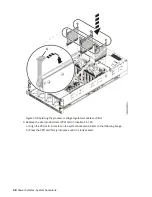
Figure 68. Routing the SAS cables
18. Remove the system-to-rail locking clips.
a) On the right rail, pull the blue latch marked R.
b) While holding the blue latch, rotate the clip off the rail.
c) Release the blue latch.
d) Repeat steps “18.a” on page 67 through “18.c” on page 67 to remove the system-to-rail locking
clip from the left rail.
19. Complete the following steps to place the system in the operating position.
a. Unlock the blue rail safety latches (A) by lifting them upward as shown in the following figure.
b. Push the system unit back into the rack as shown in the following figure until both system unit
release latches lock into position.
Note: Slide the system unit slowly into the rack to ensure that your fingers do not get caught in the
side rails.
System backplane for the 9040-MR9 67
Содержание 9040-MR9
Страница 1: ...Power Systems System backplane for the 9040 MR9 IBM...
Страница 4: ...iv...
Страница 14: ...xiv Power Systems System backplane...
Страница 17: ...or or or or System backplane for the 9040 MR9 3...
Страница 98: ...84 Power Systems System backplane...
Страница 109: ......
Страница 110: ...IBM...


