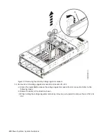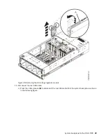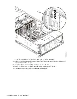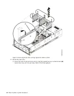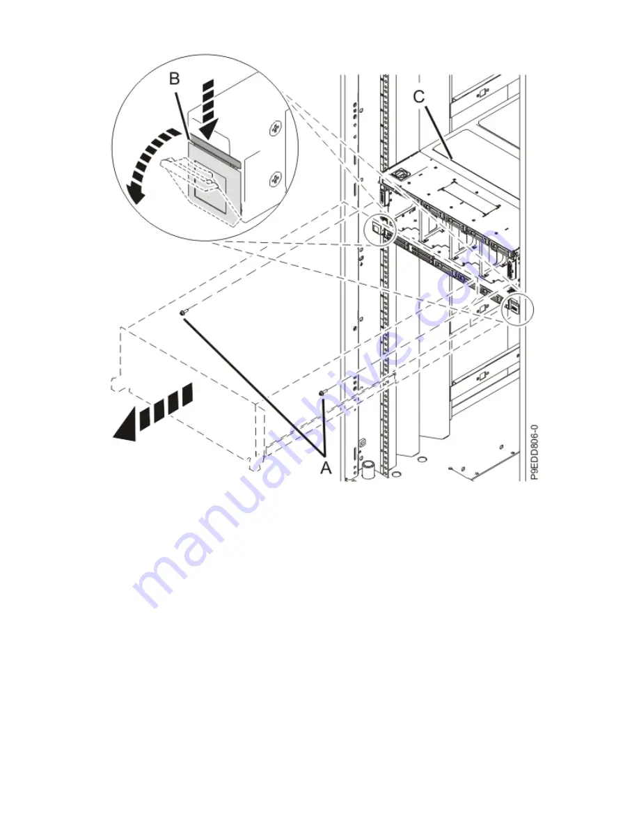
Figure 19. Placing the system in service position
6. To activate the identify LED for the faulty part, press and hold push-button (A) on the trusted
platform module card as shown in the following figure.
Verify that the LED (B) is lit, which indicates that sufficient power exists for the identify LED. If the
LED (B) is not lit, use the location code to find the physical location by using the service label.
20 Power Systems: System backplane
Содержание 9040-MR9
Страница 1: ...Power Systems System backplane for the 9040 MR9 IBM...
Страница 4: ...iv...
Страница 14: ...xiv Power Systems System backplane...
Страница 17: ...or or or or System backplane for the 9040 MR9 3...
Страница 98: ...84 Power Systems System backplane...
Страница 109: ......
Страница 110: ...IBM...


