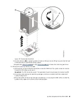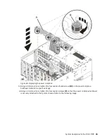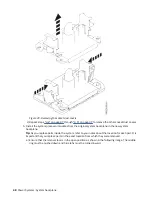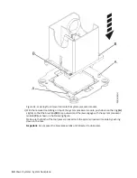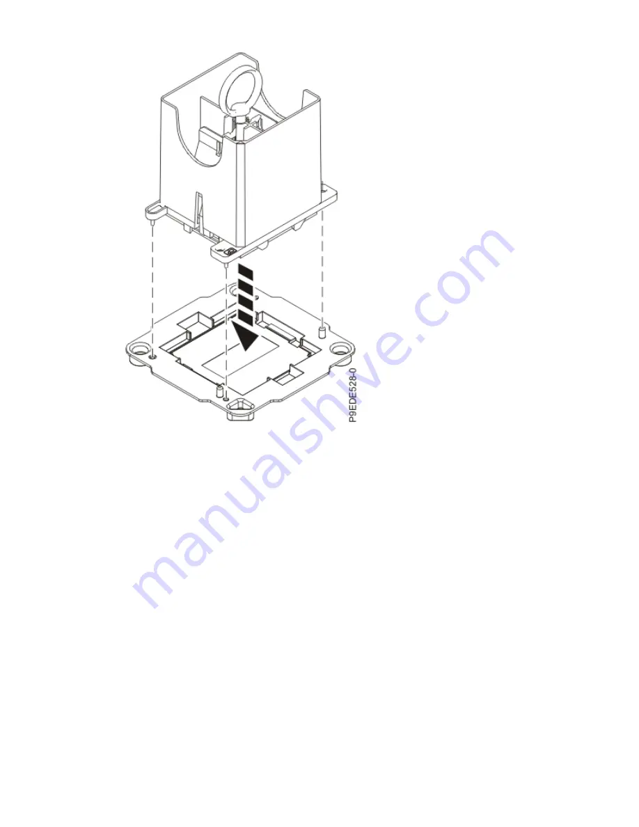
Figure 37. Placing the tool at an angle on the system processor module tray
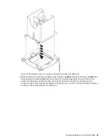
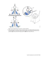
i) Release the system processor module by pushing the ring (B) downwards. Hold the ring (B) down
while pushing the blue tabs (C) inwards as shown in the following figure. Ensure that the ring
catches the openings on the blue tabs, and that the blue tabs are locked in a fixed position.
To prevent the system processor module from falling, pull up on the round lever before you place
the tool on the system processor module tray.
System backplane for the 9040-MR9 37
Содержание 9040-MR9
Страница 1: ...Power Systems System backplane for the 9040 MR9 IBM...
Страница 4: ...iv...
Страница 14: ...xiv Power Systems System backplane...
Страница 17: ...or or or or System backplane for the 9040 MR9 3...
Страница 98: ...84 Power Systems System backplane...
Страница 109: ......
Страница 110: ...IBM...


