background image

3.

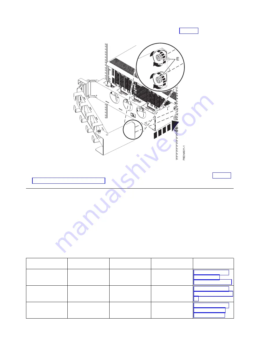
Attach the outer plate to the rails with two captive screws (E) as shown in Figure 19.

4.

Next, you must route the system cables through the cable management arm. Continue with “Cabling
the server and setting up a console.”

Cabling the server and setting up a console

Your console, monitor, or interface choices are guided by whether you create logical partitions, which
operating system you install in your primary partition, and whether you install a Virtual I/O Server
(VIOS) in one of your logical partitions.

Determining which console to use

There are different console types available to manage this server. Learn more about the consoles that are
available.

Go to the instructions for the applicable console, interface, or terminal in the following table.

Table 1. Available console types

Console type

Operating system

Logical partitions

Cable required

Cabling setup
instructions

ASCII terminal

AIX

®

, Linux, or VIOS

Yes for VIOS, no for
AIX and Linux

Serial cable equipped
with a null modem

“Cabling the server
with an ASCII
terminal” on page 19

Hardware
Management Console
(HMC)

AIX, Linux, or VIOS

Yes

Ethernet (or
cross-over cable)

“Cabling the server
to the HMC” on page
20

Integrated
Virtualization
Manager for VIOS

AIX, or Linux

Yes

Serial cable /
Ethernet cable for
LAN connection

“Cabling the server
and accessing the
IVM” on page 21

Figure 19. Attaching the outer plate to the rails

18

Power Systems: Installing the IBM Power System E850 (8408-E8E)

Содержание 8408-E8E

Страница 1: ...Power Systems Installing the IBM Power System E850 8408 E8E GI11 9913 01 IBM ...

Страница 2: ......

Страница 3: ...Power Systems Installing the IBM Power System E850 8408 E8E GI11 9913 01 IBM ...

Страница 4: ...ty Notices manual G229 9054 and the IBM Environmental Notices and User Guide Z125 5823 This edition applies to IBM Power Systems servers that contain the POWER8 processor and to all associated models Copyright IBM Corporation 2015 US Government Users Restricted Rights Use duplication or disclosure restricted by GSA ADP Schedule Contract with IBM Corp ...

Страница 5: ...essing the IVM 21 Cabling the server with keyboard video and mouse 22 Cabling the server and connecting expansion units 23 Completing the server setup 23 Completing the server setup by using an HMC 23 Completing the server setup without using an HMC 25 Setting up a preinstalled server 26 Preparing to set up your preinstalled server 26 Completing inventory for your preinstalled server 27 Removing t...

Страница 6: ...iv Power Systems Installing the IBM Power System E850 8408 E8E ...

Страница 7: ...roduct The documentation contains the safety information in your national language with references to the U S English source Before using a U S English publication to install operate or service this product you must first become familiar with the related safety information documentation You should also refer to the safety information documentation any time you do not clearly understand any safety ...

Страница 8: ...tch on power to the machine until all possible unsafe conditions are corrected v Assume that an electrical safety hazard is present Perform all continuity grounding and power checks specified during the subsystem installation procedures to ensure that the machine meets safety requirements v Do not continue with the inspection if any unsafe conditions are present v Disconnect the attached power cor...

Страница 9: ...he customer to ensure that the outlet is correctly wired and grounded to prevent an electrical shock CAUTION v Do not install a unit in a rack where the internal rack ambient temperatures will exceed the manufacturer s recommended ambient temperature for all your rack mounted devices v Do not install a unit in a rack where the air flow is compromised Ensure that air flow is not blocked or reduced ...

Страница 10: ...te potential hazards v Verify that the route that you choose can support the weight of the loaded rack cabinet Refer to the documentation that comes with your rack cabinet for the weight of a loaded rack cabinet v Verify that all door openings are at least 760 x 230 mm 30 x 80 in v Ensure that all devices shelves drawers doors and cables are secure v Ensure that the four leveling pads are raised t...

Страница 11: ...DANGER Rack mounted devices are not to be used as shelves or work spaces L002 L003 or or 1 2 3 4 or Safety notices ix ...

Страница 12: ...ION Hazardous moving parts nearby L008 All lasers are certified in the U S to conform to the requirements of DHHS 21 CFR Subchapter J for class 1 laser products Outside the U S they are certified to be in compliance with IEC 60825 as a class 1 laser product Consult the label on each part for laser certification numbers and approval information x Power Systems Installing the IBM Power System E850 8...

Страница 13: ... instruments and avoid direct exposure to the beam C030 CAUTION The battery contains lithium To avoid possible explosion do not burn or charge the battery Do Not v ___ Throw or immerse into water v ___ Heat to more than 100 C 212 F v ___ Repair or disassemble Exchange only with the IBM approved part Recycle or discard the battery as instructed by local regulations In the United States IBM has a pr...

Страница 14: ...s fingers and clothing clear when equipment is in motion v Turn Winch with hand power only If winch handle cannot be cranked easily with one hand it is probably over loaded Do not continue to turn winch past top or bottom of platform travel Excessive unwinding will detach handle and damage cable Always hold handle when lowering unwinding Always assure self that winch is holding load before releasi...

Страница 15: ...an external surge protection device SPD The dc powered system employs an isolated DC return DC I design The DC battery return terminal shall not be connected to the chassis or frame ground The dc powered system is intended to be installed in a common bonding network CBN as described in GR 1089 CORE Safety notices xiii ...

Страница 16: ...xiv Power Systems Installing the IBM Power System E850 8408 E8E ...

Страница 17: ... HMC Version 8 Release 8 3 0 or later v Graphics monitor with keyboard and mouse v Teletype TTY monitor with keyboard Completing inventory for your server Use this information to complete inventory for your server To complete the inventory complete the following steps 1 Verify that you received all the boxes you ordered 2 Unpack the server components as needed 3 Complete a parts inventory before y...

Страница 18: ... latches click into place 3 Repeat these steps for all four lift handles Installing the server into a rack You must remove components within the system chassis so that three people can lift it into the rack Install the mounting hardware first then remove components from the system chassis and then lift the chassis into place Remove the following components from the front of the system chassis v Sy...

Страница 19: ...eps 1 Use the rack mount template to determine and mark the location 2 Locate the left slide rail The left mounting slide has an L identifier stamped into the inside front location 3 At the front of the rack position the left slide rail C between the left side front and rear rack EIA mounting standards as shown in Figure 3 on page 4 4 Insert the front slide flange locator studs into the front EIA ...

Страница 20: ...ket pan head screw A placed in the middle hole 1b of the EIA rack unit as shown in Figure 3 8 Repeat steps 2 on page 3 through 7 for the right slide rail D as shown in Figure 3 The right slide rail has an R identifier stamped into the inside front location 9 Attach the two nut clips F to relative EIA locations 3b on both right and left front vertical EIA standards as shown in Figure 3 Figure 3 Att...

Страница 21: ...om the chassis so that it is easier to lift Attention v Attach an electrostatic discharge ESD wrist strap to an unpainted metal surface of your hardware to prevent the electrostatic discharge from damaging your hardware v When using an ESD wrist strap follow all electrical safety procedures An ESD wrist strap is used for static control It does not increase or decrease your risk of receiving electr...

Страница 22: ...m as shown in Figure 5 Removing the front cover Learn how to remove the front cover To remove the front cover complete the following steps 1 Go to the front of the system chassis 2 Place your fingers on the indentations B located on both sides of the cover Figure 5 Removing a power supply from the rear of the system chassis 6 Power Systems Installing the IBM Power System E850 8408 E8E ...

Страница 23: ...n how to remove the system fans To remove the system fans complete the following steps 1 Rotate the fan handle A in the direction shown in Figure 7 on page 8 to unlock the fan from its slot Figure 6 Removing the front cover Installing the IBM Power System E850 8408 E8E 7 ...

Страница 24: ...he system fans Removing the disk drive backplane Learn how to remove the disk drive backplane To remove the disk drive backplane complete the following steps 1 Use the included 4mm Allen hand tool to loosen the 2 captive shipping screws on the RAID assembly Figure 7 Removing the front fan 8 Power Systems Installing the IBM Power System E850 8408 E8E ...

Страница 25: ...he thumbscrews on the RAID assembly to loosen them as shown in Figure 9 3 Pull out the latches and remove the disk drive backplane from the system Figure 8 Loosening the captive shipping screws Figure 9 Removing the RAID assembly from the system Installing the IBM Power System E850 8408 E8E 9 ...

Страница 26: ...handle up B until the latches click into place 3 Repeat these steps for all four lift handles Installing the system into the rack Use the procedure in this section to install the system into the rack The procedure includes information that is intended to promote safety and reliable operation CAUTION This system requires three people to install the system into the rack To install the system into th...

Страница 27: ...n as shown in Figure 11 5 Tilt the front of the system down so that the chassis pins are inserted into the front 4 and 5 and middle holes in the mounting hardware as shown in as shown in Figure 11 6 Remove the lift handles on both sides of the chassis and store them for future use 7 Release the latches in the middle of the rails and push the system all the way into the rack as shown in Figure 12 o...

Страница 28: ...not increase or decrease your risk of receiving electric shock when using or working on electrical equipment v If you do not have an ESD wrist strap just prior to removing the product from ESD packaging and installing or replacing hardware touch an unpainted metal surface of the system for a minimum of 5 seconds Replacing the disk drive backplane Learn how to replace the disk drive backplane To re...

Страница 29: ...f the rack Ensure that the fan handle A is rotated open in the direction shown in Figure 14 on page 14 2 Using your hand to support the bottom of the fan align the fan with the fan slot and slide it into the system 3 Rotate the fan handle A in the direction shown and then press the fan handle until the latch locks in place See Figure 14 on page 14 Figure 13 Replacing the disk drive backplane at th...

Страница 30: ...complete the following steps 1 Move to the front of the rack 2 Position the cover A on the front of the system unit so that the four pins on the system match the four holes on the rear of the cover Figure 14 Replacing a front fan 14 Power Systems Installing the IBM Power System E850 8408 E8E ...

Страница 31: ...eps 1 Ensure that you have the electrostatic discharge ESD wrist strap attached If not attach it now 2 Move to the rear of the rack 3 Align the power supply A with the bay and slide the power supply into the system until the terracotta latch B locks in place as shown in Figure 16 on page 16 Figure 15 Installing the front cover Installing the IBM Power System E850 8408 E8E 15 ...

Страница 32: ... complete the following steps 1 Attach the inner plate A to the system chassis by hand tightening the two captive screws B through the threaded holes on the chassis as shown in Figure 17 on page 17 Then use the T25 hex tool that was included with your system to tighten the bolts further Figure 16 Replacing a power supply in the system 16 Power Systems Installing the IBM Power System E850 8408 E8E ...

Страница 33: ...clips C to the rack rail in the location where you will be attaching the outer plate to the to the rail as shown in Figure 18 Figure 17 Attaching the inner plate to the system chassis Figure 18 Attaching the nut clips to the rack rail Installing the IBM Power System E850 8408 E8E 17 ...

Страница 34: ... about the consoles that are available Go to the instructions for the applicable console interface or terminal in the following table Table 1 Available console types Console type Operating system Logical partitions Cable required Cabling setup instructions ASCII terminal AIX Linux or VIOS Yes for VIOS no for AIX and Linux Serial cable equipped with a null modem Cabling the server with an ASCII ter...

Страница 35: ...omplete the following steps 1 Using a serial cable that is equipped with a null modem connect the ASCII terminal to the serial port on the rear of the server 2 Complete the following steps a Plug the power cord into the power supply b Plug the system power cords and the power cords for any other attached devices into the power source Note Confirm that the system is in standby mode The green power ...

Страница 36: ...e of capacity on demand Using service applications the HMC can also communicate with managed systems to detect consolidate and forward information to IBM service for analysis If you have not installed and configured your HMC do so now For instructions see Installation and configuration scenarios http www ibm com support knowledgecenter POWER8 p8hai basichmcinstallationandconfigurationtaskflow htm ...

Страница 37: ... to the Ethernet port that is labeled HMC2 T5 on the managed server 4 Continue with Cabling the server and connecting expansion units on page 23 Cabling the server and accessing the IVM When you install the Virtual I O Server VIOS in an environment where no Hardware Management Console HMC is present the VIOS automatically creates a management partition whose interface is the Integrated Virtualizat...

Страница 38: ...to the optical device and press Enter e Select the device number that corresponds to the optical device and press Enter f Select Normal Boot and confirm that you want to exit SMS 5 Install the Virtual I O Server a Select the console and press Enter b Select a language for the BOS menus and press Enter c Select Start Install Now with Default Settings d Select Continue with Install The managed syste...

Страница 39: ...e flashing check the power cord connections 2 If you have an expansion unit that you need to install install it now For information about connecting enclosures and expansion units see Enclosures and expansion units http www ibm com support knowledgecenter POWER8 p8ham p8ham_kickoff htm Completing the server setup Learn about the tasks you must complete to set up your managed system Select from the...

Страница 40: ...s If you are using an HMC Enhanced interface complete the following steps a In the navigation area click the Resources icon and then select All Systems b To view the actions for that server select the server name of the required server c In the navigation area click System Actions Operations Launch Advanced System Management ASM d Log on to the ASMI by using the administrator user ID and password ...

Страница 41: ... configurations save it to the template library and deploy the partition template For more information see Partition templates http www ibm com support knowledgecenter POWER8 p8efc p8efc_partition_template_concept htm v If you want to use an existing template from another source you can import that and use it For more information see Importing a partition template http www ibm com support knowledg...

Страница 42: ...tarting a system that is not managed by an HMC http www ibm com support knowledgecenter POWER8 p8haj startsysnohmc htm 3 Install an operating system and update the operating system v Install the AIX operating system For instructions see Installing AIX http www ibm com support knowledgecenter POWER8 p8hdx p8hdx_installaix htm v Install the Linux operating system For instructions see Installing Linu...

Страница 43: ... before you install the server 1 Ensure that you have the following items before you start your installation v Phillips screwdriver v Flat head screwdriver v Wire cutter 2 Ensure that you have one of the following consoles v Hardware Management Console HMC Ensure that your HMC is at version 8 release 8 3 0 or later v Graphic monitor with keyboard and mouse v Teletype tty monitor with keyboard Comp...

Страница 44: ...e management arm c Secure the cord and cables with cable ties or hook and loop fasteners B as shown in Figure 21 d If you have a disk drive enclosure or expansion drawer that came preinstalled in this rack use the documentation supplied with these options For information about connecting enclosures and expansion units see Enclosures and expansion units http www ibm com support knowledgecenter POWE...

Страница 45: ... Virtual I O Server VIOS in one of your logical partitions Determining which console to use There are different console types available to manage this server Learn more about the consoles that are available Go to the instructions for the applicable console interface or terminal in the following table Table 3 Available console types Console type Operating system Logical partitions Cable required Ca...

Страница 46: ... on the system see Part locations and location codes http www ibm com support knowledgecenter POWER8 p8ecs p8ecs_locations htm To cable an ASCII terminal to the server complete the following steps 1 Using a serial cable that is equipped with a null modem connect the ASCII terminal to the serial port on the rear of the server 2 Complete the following steps a Plug the power cord into the power suppl...

Страница 47: ...R8 processor based servers the HMC must be at version 8 release 8 3 0 or later To view the HMC version and release complete the following steps 1 In the navigation area click Updates 2 In the work area view and record the information that appears in the HMC Code Level section including the HMC version release Service Pack build level and base versions If you need to update your HMC version and rel...

Страница 48: ... on the server For details see Cabling the server with an ASCII terminal on page 30 2 Complete the following steps a Verify that you have access to the Advanced System Management Interface ASMI by using the web interface For details see Accessing the ASMI using a web browser b Verify that you have administrator or authorized service provider authority in ASMI c Using the Web based ASMI change the ...

Страница 49: ...1 Locate the graphics card and USB ports at the rear of the system The USB ports are located next to slot 1 on the rear I O cage Note The USB ports on the FSP2 card are not used for keyboard and mouse connection 2 Connect the monitor cable to the graphics card 3 Connect a keyboard and mouse to the USB ports 4 Power on the console 5 Continue with Cabling the server and connecting expansion units on...

Страница 50: ...d system http www ibm com support knowledgecenter POWER8 p8hai setpasswordsforthemanagedsystem htm For more information about setting passwords for the managed system by using the HMC Enhanced interface see Setting passwords for the managed system http www ibm com support knowledgecenter POWER8 p8hai p8hai_setpassword_enh htm 2 Update the time of day on the managed system by using the Advanced Sys...

Страница 51: ...b In the contents pane select the required managed system c Click Tasks Operations Power On Follow any additional on screen instructions If you are using an HMC Enhanced interface complete the following steps a In the navigation area click the Resources icon and then select All Systems b In the content pane select the required managed system name c In the navigation area click System Actions Opera...

Страница 52: ...r POWER8 p8hby connect_asmi htm b On the ASMI Welcome pane note the existing level of server firmware in the upper right corner under the copyright statement c Update the time of day In the navigation area expand System Configuration d Click Time of Day The content pane displays a form that shows the current date month day and year and time hours minutes and seconds e Change the date value the tim...

Страница 53: ...w ibm com support knowledgecenter POWER8 p8ha5 fix_firm_no_hmc_aix htm v If you are using VIOS see Updating the Virtual I O Server s firmware and device microcode with an Internet connection http www ibm com support knowledgecenter POWER8 p8ha5 fix_virtual_firm_ivm htm 6 You have now completed the steps to install your server Installing the IBM Power System E850 8408 E8E 37 ...

Страница 54: ...38 Power Systems Installing the IBM Power System E850 8408 E8E ...

Страница 55: ...LIED WARRANTIES OF NON INFRINGEMENT MERCHANTABILITY OR FITNESS FOR A PARTICULAR PURPOSE Some states do not allow disclaimer of express or implied warranties in certain transactions therefore this statement may not apply to you This information could include technical inaccuracies or typographical errors Changes are periodically made to the information herein these changes will be incorporated in n...

Страница 56: ...ations performed and data saved or transmitted by the system at or near the time of the outage or failure In addition users must establish procedures to ensure that there is independent data verification before relying on such data in sensitive or critical operations Users should periodically check IBM s support websites for updated information and fixes applicable to the system and related softwa...

Страница 57: ...e limits are designed to provide reasonable protection against harmful interference when the equipment is operated in a commercial environment This equipment generates uses and can radiate radio frequency energy and if not installed and used in accordance with the instruction manual may cause harmful interference to radio communications Operation of this equipment in a residential area is likely t...

Страница 58: ...email halloibm de ibm com Warning This is a Class A product In a domestic environment this product may cause radio interference in which case the user may be required to take adequate measures VCCI Statement Japan The following is a summary of the VCCI Japanese statement in the box above This is a Class A product based on the standard of the VCCI Council If this equipment is used in a domestic env...

Страница 59: ... need to perform practical action Electromagnetic Interference EMI Statement Taiwan The following is a summary of the EMI Taiwan statement above Warning This is a Class A product In a domestic environment this product may cause radio interference in which case the user will be required to take adequate measures IBM Taiwan Contact Information Electromagnetic Interference EMI Statement Korea Notices...

Страница 60: ...ann vom Betreiber verlangt werden angemessene Maßnahmen zu ergreifen und dafür aufzukommen Deutschland Einhaltung des Gesetzes über die elektromagnetische Verträglichkeit von Geräten Dieses Produkt entspricht dem Gesetz über die elektromagnetische Verträglichkeit von Geräten EMVG Dies ist die Umsetzung der EU Richtlinie 2004 108 EG in der Bundesrepublik Deutschland Zulassungsbescheinigung laut dem...

Страница 61: ... following measures v Reorient or relocate the receiving antenna v Increase the separation between the equipment and receiver v Connect the equipment into an outlet on a circuit different from that to which the receiver is connected v Consult an IBM authorized dealer or service representative for help Properly shielded and grounded cables and connectors must be used in order to meet FCC emission l...

Страница 62: ...its for Class B equipment were derived for typical residential environments to provide reasonable protection against interference with licensed communication equipment European Community contact IBM Deutschland GmbH Technical Regulations Department M372 IBM Allee 1 71139 Ehningen Germany Tele 49 0 800 225 5423 or 49 0 180 331 3233 email halloibm de ibm com VCCI Statement Japan Japanese Electronics...

Страница 63: ...hland Einhaltung des Gesetzes über die elektromagnetische Verträglichkeit von Geräten Dieses Produkt entspricht dem Gesetz über die elektromagnetische Verträglichkeit von Geräten EMVG Dies ist die Umsetzung der EU Richtlinie 2004 108 EG in der Bundesrepublik Deutschland Zulassungsbescheinigung laut dem Deutschen Gesetz über die elektromagnetische Verträglichkeit von Geräten EMVG bzw der EMC EG Ric...

Страница 64: ...t the express consent of IBM Rights Except as expressly granted in this permission no other permissions licenses or rights are granted either express or implied to the publications or any information data software or other intellectual property contained therein IBM reserves the right to withdraw the permissions granted herein whenever in its discretion the use of the publications is detrimental t...

Страница 65: ...Notices 49 ...

Страница 66: ...IBM Part Number 00RW900 Printed in USA GI11 9913 01 1P P N 00RW900 ...

Отзывы: