v
Clamps
v
Plastic straps
v
Hook-and-loop fasteners
Power cord retainers are typically found at the rear of the unit and on the chassis or pedestal near the
alternating current (AC) power cord input.
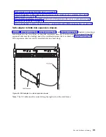
Systems that are rack mounted and are on rails should use the provided cable management arm.
Systems that are rack mounted, but are not on rails should use the provided rings, clamps, or straps.
Planning for serial-attached SCSI cables
Serial-attached SCSI (SAS) cables provide serial communication for transfer of data for directly attached
devices, such as hard disk drives, solid-state drives, and CD-ROM drives.
SAS cable overview
Serial-attached SCSI (SAS) is an evolution of the parallel SCSI device interface into a serial point-to-point
interface. SAS physical links are a set of four wires that are used as two differential signal pairs. One
differential signal transmits in one direction while the other differential signal transmits in the opposite
direction. Data might be transmitted in both directions simultaneously. SAS physical links are contained
in ports. A port contains one or more SAS physical links. A port is a wide port if there are more than one
SAS physical link in the port. Wide ports are designed to enhance performance and provide redundancy
in case an individual SAS physical link fail.
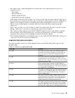
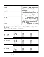
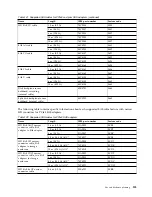
There are two types of SAS connectors, mini SAS and mini SAS high density (HD). High-density cables
are typically needed to support 6 Gb/s SAS.
Each SAS cable contains four SAS physical links that are typically organized into either a single 4x SAS
port or two 2x SAS ports. Each end of the cable uses a mini SAS or mini SAS HD 4x connector. Review
the following design and installation criteria before you install SAS cables:
v
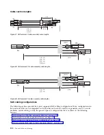
Only specific cabling configurations are supported. Many configurations can be constructed that are
not supported and will either not function correctly or generates errors. See “SAS cabling
configurations” on page 128 for figures of the supported cabling configurations.
v
Each mini-SAS 4x connector is keyed to help prevent cabling an unsupported configuration.
v
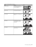
HD SAS cables have a key that prevents the cable retention from latching if the cable is oriented
incorrectly. HD SAS cables will slide in easily and latch correctly if they are inserted with the blue
release tab on the right side of the card connector.
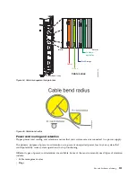
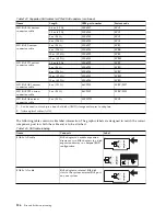
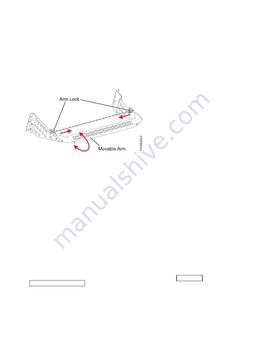
Figure 56. Cable management bracket
122
Site and hardware planning
Содержание 8408-44E
Страница 1: ...Power Systems Site and hardware planning IBM...
Страница 2: ......
Страница 3: ...Power Systems Site and hardware planning IBM...
Страница 16: ...xiv Site and hardware planning...
Страница 18: ...2 Site and hardware planning...
Страница 22: ...6 Site and hardware planning...
Страница 51: ...Figure 19 Model 0555 and 7014 S25 plan view Site and hardware planning 35...
Страница 192: ...176 Site and hardware planning...
Страница 204: ...188 Site and hardware planning...
Страница 205: ......
Страница 206: ...IBM Printed in USA...

