


Removal and Replacement
4-65
System Interface Board (SIB)
Attention: Lateral planar 2 and system interface board (SIB) EEPROMs contain the SYSID
of the system. When one of the two components is to be replaced (for example the Lateral
Planar 2), the SYSID information is copied from SIB EEPROM into the lateral planar 2
EEPROM when you start the system.
To avoid loosing this information, it is not possible to replace both components at the same
time.
When both components are to be replaced, proceed as follows:
1. First substitute the SIB and start up the system: the SYSID information is copied from
the lateral planar 2 EEPROM to the SIB EEPROM.
2. Substitute the lateral planar 2 and start up the system: the SYSID information is copied
from SIB EEPROM to the Lateral Planar 2 EEPROM.
Note: Refer to “Handling Static-Sensitive Devices” on page 4-14 before removing or
installing the SIB.
Removal
1. Depending on the type of power distribution in your rack, do one of the following:
•
“Power-Off Procedure with a Power Distribution Bus” on page 4-2.
•
“Power-Off Procedure with a Power Distribution Unit” on page 4-5.
•
“Power-Off Procedure with a Power Distribution Panel” on page 4-9.
2. Remove the two mounting screws.
3. Pull the SIB toward you until the SIB disengages, and then remove it from the CPU
enclosure.
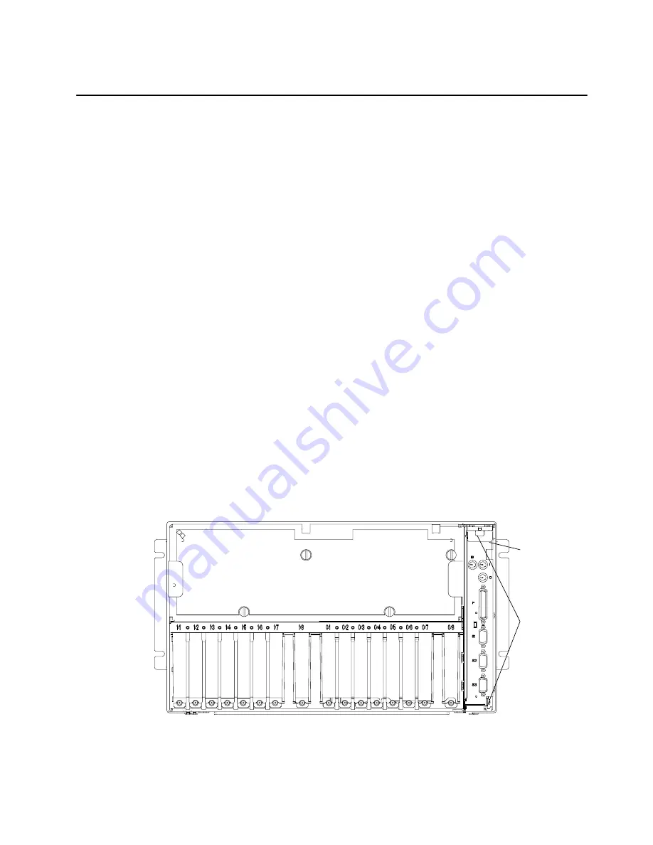
Rear View of CPU Enclosure
Mounting
Screws
System
Interface
Board
Содержание 7015-R50
Страница 1: ...7015 Models R30 R40 and R50 CPU Enclosure Installation and Service Guide...
Страница 10: ...x Service Guide...
Страница 14: ...xiv Service Guide...
Страница 34: ...1 20 Service Guide...
Страница 206: ...6 2 Service Guide Detail 1 Front Bezel Front Access Plate and CPU Enclosure 1 2 3 4 5 10 11 12 6 10 11 12 9 7 8...
Страница 210: ...6 6 Service Guide Detail 3 Media Module 1 21 22 2 3 7 6 5 4 13 9 8 20 16 14 10 15 17 11 18 23 24 19 12...
Страница 212: ...6 8 Service Guide Detail 4 CPU Module 1 of 3 17 18 19 3 12 1 2 5 6 4 7 20 21 22 14 8 9 10 16 15 24 25 11 13 23...
Страница 214: ...6 10 Service Guide Detail 5 CPU Module 2 of 3 26 27 29 30 31 32 33 34 28 35...
Страница 216: ...6 12 Service Guide Detail 6 CPU Module 3 of 3 36 37...
Страница 252: ...B 8 Installation and Service Guide...
Страница 288: ...Service Guide D 30...
Страница 299: ......
Страница 300: ...Printed in the U S A SA23 2743 02 40H7126...


