


Removal and Replacement
4-61
Power Supply or Cooling Unit for Systems
Attention: If your system has the capability to change power supplies while the system
power is applied (R40, R50), see “Removal and Replacement While System Power is
Applied” on page 4-62.
Removal While System Power is Removed
The power supply position farthest from the system interface board can contain
either an optional power supply or a cooling unit.
DANGER
Do not attempt to open the covers of the power supply. The power supply is
not serviceable and is to be replaced as a unit.
Notes:For a translation of these notices, refer to the
System Unit Safety Information
manual, form number SA23-2652.
1. Perform the “Rear Access Plate” removal procedure on page 4-60.
Note: The power distribution system in the 7015 Model R00 rack can contain either a
power distribution bus, power distribution unit, or a power distribution panel.
Attention: This unit may have more than one power supply cord. To completely remove
power, you must disconnect all power supply cords.
2. If you are removing the power supply, disconnect the power supply power cord from the
power distribution system installed in your rack.
3. Loosen the docking screw until the screw is disengaged.
4. Slowly pull the power supply or cooling unit toward you until you can place a hand under
it for support, and then remove the power supply or cooling unit from the CPU enclosure.
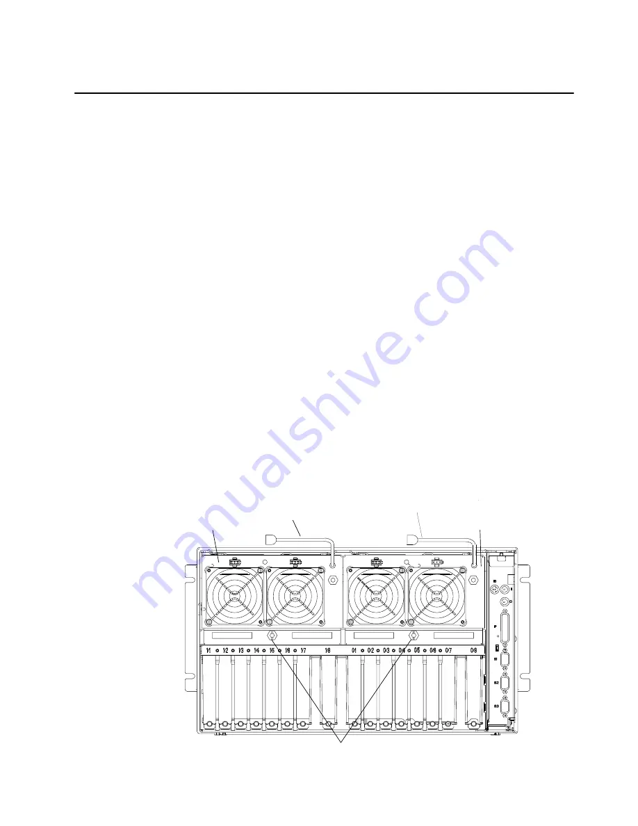
Rear View of CPU Enclosure
Power Supply
Cooling Unit or
Power Supply
Power Supply Power Cord
(Only with Power Supply)
Power Supply Power Cord
(Only with Power Supply)
Docking Screws
Содержание 7015-R50
Страница 1: ...7015 Models R30 R40 and R50 CPU Enclosure Installation and Service Guide...
Страница 10: ...x Service Guide...
Страница 14: ...xiv Service Guide...
Страница 34: ...1 20 Service Guide...
Страница 206: ...6 2 Service Guide Detail 1 Front Bezel Front Access Plate and CPU Enclosure 1 2 3 4 5 10 11 12 6 10 11 12 9 7 8...
Страница 210: ...6 6 Service Guide Detail 3 Media Module 1 21 22 2 3 7 6 5 4 13 9 8 20 16 14 10 15 17 11 18 23 24 19 12...
Страница 212: ...6 8 Service Guide Detail 4 CPU Module 1 of 3 17 18 19 3 12 1 2 5 6 4 7 20 21 22 14 8 9 10 16 15 24 25 11 13 23...
Страница 214: ...6 10 Service Guide Detail 5 CPU Module 2 of 3 26 27 29 30 31 32 33 34 28 35...
Страница 216: ...6 12 Service Guide Detail 6 CPU Module 3 of 3 36 37...
Страница 252: ...B 8 Installation and Service Guide...
Страница 288: ...Service Guide D 30...
Страница 299: ......
Страница 300: ...Printed in the U S A SA23 2743 02 40H7126...


