background image

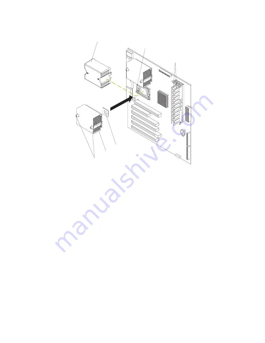
Installing the additional microprocessor

Complete the following steps to install an additional microprocessor.

DIMMs

Microprocessor
release lever

Captive screws

Heatsink 2

Microprocessor 2

Microprocessor
baffle

1. Review the safety information beginning on page vii, “Installation guidelines” on

page 27, and “Handling static-sensitive devices” on page 28.

2. Turn off the computer and all attached devices.

3. Disconnect all power cords; then disconnect all external cables.

4. Remove the side cover (see “Removing the side cover” on page 31).

5. Remove the support bracket (“Removing and installing the support bracket” on

page 33).

6. Remove the air baffle by unhooking it from its retaining tabs and lifting it off the

chassis.

7. Locate the second microprocessor socket (connector CPU2) on the system

board.

8. Remove the microprocessor baffle from the second microprocessor socket.

9. If the second microprocessor socket is covered with protective film, peel and

remove the film.

10. Install the microprocessor:

a. Touch the static-protective package containing the new microprocessor to

any

unpainted

metal surface on the computer; then, remove the

microprocessor from the package.

b. Pull out and lift up on the microprocessor-release lever to unlock the

microprocessor socket.

Chapter 4. Installing options

49

Содержание 622138U - IntelliStation Z - Pro 6221

Страница 1: ...User s Guide Type 6221 IntelliStation Z Pro...

Страница 2: ......

Страница 3: ...IBM IntelliStation Z Pro Type 6221 User s Guide SC02 R303 50...

Страница 4: ...Warranty information on page 95 and Appendix C Notices on page 107 Second Edition December 2002 Copyright International Business Machines Corporation 2002 All rights reserved US Government Users Rest...

Страница 5: ...nced Diagnostics diskette 14 Using video features 15 Video device drivers 15 Changing monitor settings 15 Using audio features 16 Using security features 16 Anti intrusion features 16 Component protec...

Страница 6: ...onnectors 55 Auxiliary device pointing device connector 56 Ethernet RJ 45 connector 56 IEEE 1394 FireWire connectors 56 Keyboard connector 57 Parallel connector 57 Serial connectors 58 Ultra320 SCSI c...

Страница 7: ...93 Getting help and information from the World Wide Web 93 Software service and support 94 Hardware service and support 94 Appendix B Warranty information 95 Warranty period 95 Problem determination 9...

Страница 8: ...vi IBM IntelliStation Z Pro Type 6221 User s Guide...

Страница 9: ...tuotteen lue turvaohjeet kohdasta Safety Information Avant d installer ce produit lisez les consignes de s curit Vor der Installation dieses Produkts die Sicherheitshinweise lesen Prima di installare...

Страница 10: ...cables as described in the following table when installing moving or opening covers on this product or attached devices To connect 1 Turn everything OFF 2 First attach all cables to devices 3 Attach...

Страница 11: ...aser products contain an embedded Class 3A or Class 3B laser diode Note the following Laser radiation when open Do not stare into the beam do not view directly with optical instruments and avoid direc...

Страница 12: ...ceable parts inside these components If you suspect a problem with one of these parts contact a service technician Statement 23 CAUTION Do not place any object weighing more than 50 kg 110 lb on top o...

Страница 13: ...f Rack Einheiten ablegen 50 kg Notice n 23 ATTENTION Ne posez pas d objet dont le poids d passe 50 kg sur les unit s mont es en armoire 50 kg Varningsmeddelande 23 VARNING Placera inte n got f rem l s...

Страница 14: ...binett 50 kg Avviso 23 ATTENZIONE Non poggiare oggetti che pesano pi di 50 kg sulla parte superiore delle unit montate in rack 50 kg Turvaohje 23 Varoitus Telineeseen asennettujen laitteiden p lle ei...

Страница 15: ...ie in het rek zijn gemonteerd 50 kg Forskrift 23 Pas p Anbring ikke genstande der vejer mere end 50 kg oven p enheder der er monteret i rack 50 kg Instru o 23 CUIDADO N o coloque nenhum objeto com pes...

Страница 16: ...23 50 110 50 110 xiv IBM IntelliStation Z Pro Type 6221 User s Guide...

Страница 17: ...23 50 50 23 50 50 23 50 110 50 110 Safety xv...

Страница 18: ...50 Kg 50 23 23 50 110 50 110 23 50 110 50 110 xvi IBM IntelliStation Z Pro Type 6221 User s Guide...

Страница 19: ...23 50 50 23 50 110 50 110 23 50 110 50 110 Safety xvii...

Страница 20: ...23 50 50 110 23 50 110 50 110 xviii IBM IntelliStation Z Pro Type 6221 User s Guide...

Страница 21: ...23 50 110 50 110 Instru o 23 CUIDADO N o coloque nenhum objeto com peso superior a 50 kg 110 lbs sobre dispositivos montados em rack 50 kg 110 lbs Safety xix...

Страница 22: ...xx IBM IntelliStation Z Pro Type 6221 User s Guide...

Страница 23: ...ements used in this book The caution and danger statements used in this book also appear in the multilingual Safety Information book that is viewable through Access IBM and on the IBM IntelliStation D...

Страница 24: ...are Maintenance Manual This publication contains information for trained service technicians It can be found at http www ibm com pc support on the World Wide Web v Readme files on the Device Drivers a...

Страница 25: ...t front and rear Mic front and rear Line in rear v ATA 100 dual channel IDE controller Video adapter Accelerated graphics port AGP Pro 50 video with one of the following v Matrox Millennium G450 DVI I...

Страница 26: ...strator or file server can use to remotely manage and control your computer Some of the features include Wake on LAN Remote Administration IBM Director Agent and System Migration Assistant See Managin...

Страница 27: ...ools that you can use within your Windows operating system In addition to isolating hardware problems these tools provide information about your computer operating environment and some software compon...

Страница 28: ...em Lotus SmartSuite Lotus SmartSuite contains a package of powerful award winning productivity applications and everything you need to access the Internet Your IntelliStation Z Pro computer comes with...

Страница 29: ...ater chapters of this publication v 24 hours a day 7 days a week customer support v 3 year limited warranty v Advanced Configuration and Power Interface ACPI v Advanced Desktop Management Interface DM...

Страница 30: ...bezel and diagnostics LEDs on the system board v Upgradeable basic input output system BIOS and POST v Vital product data VPD includes serial number information and replacement part numbers stored in...

Страница 31: ...from the CD ROM drive CD ROM drive activity LED When this LED is lit it indicates that the CD ROM drive is in use Diskette drive activity LED When this LED is lit it indicates that the diskette drive...

Страница 32: ...pter 5 Solving problems on page 61 for additional information USB ports Use these automatically configures ports to connect universal serial bus USB v2 0 devices to your computer using Plug and Play t...

Страница 33: ...might not see Press F1 for Configuration Setup If you want to see the prompt see instructions for displaying the prompt in Using the Configuration Setup Utility program on page 21 Use the Configuratio...

Страница 34: ...ed To install another operating system follow the instructions in the documentation provided with the operating system If you are installing another Microsoft Windows operating system follow the instr...

Страница 35: ...ing address if you do not have access to the Internet Using Access IBM Access IBM is an interface through which you can quickly access information or perform specific tasks The choices available from...

Страница 36: ...ette using Access IBM by downloading a program image from the World Wide Web or from the Device Drivers and IBM Enhanced Diagnostics CD Complete the following steps to create the diagnostics diskette...

Страница 37: ...need information about obtaining and installing updated device drivers For more information about installing device drivers see Recovering or installing device drivers on page 87 Changing monitor set...

Страница 38: ...is connector receives stereo audio signals from external devices such as the line output from a stereo television or a musical instrument One line in connector is on the rear of the computer Line out...

Страница 39: ...backed up and the drive replaced Virus protection Your computer has built in virus protection that can be enabled through the Configuration Setup Utility program This built in protection checks for vi...

Страница 40: ...ck Systems Management from the topics on the left Scroll down and click on a systems management tool to get more details IBM Director Agent The IBM Director Agent streamlines and automates personal co...

Страница 41: ...ngle set of applications that can be deployed to different user groups while taking into account the users application needs Shutting down your operating system When you are ready to turn off the comp...

Страница 42: ...can turn off your computer from the operating system If this feature is supported by your operating system it will turn off the computer after performing an orderly shutdown of the operating system T...

Страница 43: ...d configure your disk array subsystem before you install your operating system See Using ServeRAID Manager on page 25 for more information v Ethernet controller configuration process To configure the...

Страница 44: ...the microprocessor and the amount of memory that is installed System summary information appears on both the full and limited Configuration Setup Utility menus Changes that you make to configuration s...

Страница 45: ...ether the computer starts with the keyboard number lock on or off The computer uses a startup sequence to determine the device from which the operating system starts For example you can define a start...

Страница 46: ...r However if you want to change the settings in the Configuration Setup Utility program you must type the administrator password to access the full configuration menus If you type the user password yo...

Страница 47: ...ress Enter The Device Properties and Mirroring Properties choices produce additional screens of parameters to review or change Formatting a SCSI hard disk drive Low level formatting removes all data f...

Страница 48: ...use the ServerGuide Setup and Installation CD to configure the optional controllers 2 To update the firmware and BIOS for an optional ServeRAID controller you must use the IBM ServeRAID Support CD th...

Страница 49: ...from the computer See Moving the stabilizing feet on page 30 for more information v The blue color on components and labels identifies touch points where you can grip a component move a latch and so...

Страница 50: ...ted metal part of the computer for at least 2 seconds This drains static electricity from the package and from your body v Remove the device from its package and install it directly into the computer...

Страница 51: ...EEE 1394 FireWire adapter Mini PCI type III slot 6 PCI6 System board internal connectors The following illustration shows the internal connectors on the system board Rear fan 1 SYSFAN1 Ethernet activi...

Страница 52: ...s This section provides instructions for installing hardware options in your computer Moving the stabilizing feet The two front feet on the bottom of the computer rotate 90 degrees to provide addition...

Страница 53: ...see Turning off the computer on page 20 3 Disconnect all power cords then disconnect all external cables 4 Unlock the side cover then pull the cover release latch away from the computer and push the c...

Страница 54: ...er on page 31 2 Locate the bezel release lever then press the bezel release lever toward the front of the computer 3 Pull the top of the bezel away from the chassis then push the bezel down to disenga...

Страница 55: ...ls have an IEEE 1394 FireWire adapter installed in mini PCI slot 6 PCI6 You can install up to five additional optional adapters in your computer in PCI slot 1 PCI1 and PCI X slots 2 through 5 PCI2 thr...

Страница 56: ...the PCI devices in the following order if you have not changed the default startup sequence AGP slot mini PCI slot 6 PCI expansion slot 1 system board integrated drive electronics IDE or SCSI devices...

Страница 57: ...the adapter by the top edge or upper corners and align it with the expansion slot guides then press the adapter firmly into the expansion slot Move the adapter directly from the static protective pack...

Страница 58: ...r to control the internal hard disk drives With a SCSI adapter installed you can configure the internal hard disk drives into disk arrays You can also cable a SCSI adapter to external hard disk drives...

Страница 59: ...tors on page 29 for the location of the SCSI LED connector Rear adapter retention bracket Front adapter retention bracket SCSI Adapter SCSI activity indicator cable SCSI signal cable connector SCSI ac...

Страница 60: ...1 2 and 3 only 2 The integrated IDE controller in your computer supports the connection of up to four IDE devices 3 You can install a 3 5 in slim high or 5 25 in half high removable media drive such...

Страница 61: ...n off the computer and all attached devices 3 Disconnect all power cords then disconnect all external cables 4 Remove the side cover see Removing the side cover on page 31 5 Remove the support bracket...

Страница 62: ...e that the other end of this cable is connected into the appropriate IDE or SCSI connector on the system board See Power and signal cables for internal drives on page 43 for additional information abo...

Страница 63: ...b of the drive aligns with the oval cutout and the drive locks into place then connect the cables at the rear of the drive 10 If you have other options to install or remove do so now 11 Replace the su...

Страница 64: ...or SCSI device then connect one end of the appropriate signal cable into the back of the drive and make sure that the other end of this cable is connected into the appropriate IDE or SCSI connector on...

Страница 65: ...ve ensure that one of the drive connectors of the signal cable is connected to the drive and that the connector at the other end of the signal cable is connected to the system board v The computer has...

Страница 66: ...r computer is an easy way to make programs run faster You can increase the amount of memory in your computer by installing memory modules Your IntelliStation Z Pro computer uses industry standard PC21...

Страница 67: ...side cover on page 31 5 Remove the support bracket see Removing and installing the support bracket on page 33 6 You might find it easier to install memory modules if you rotate the drive cage out of...

Страница 68: ...etaining clips remove the DIMM then reinsert it DIMM 1 DIMM 3 DIMM 2 DIMM 4 12 If you have other options to install or remove do so now 13 Push the drive cage outward and press in on the drive cage re...

Страница 69: ...your computer to determine the specific type of microprocessor on your system board Important A microprocessor must always be installed in socket CPU1 of the system board Notes 1 To order additional...

Страница 70: ...e Manager button d On the Device Manager window click on the plus sign next to the Computer node to expand the list then double click on ACPI Uniprocessor PC e On the Advanced Configuration and Power...

Страница 71: ...e support bracket Removing and installing the support bracket on page 33 6 Remove the air baffle by unhooking it from its retaining tabs and lifting it off the chassis 7 Locate the second microprocess...

Страница 72: ...the plastic cover and do not touch the thermal grease on the bottom of the heat sink Touching the thermal grease will contaminate it If the thermal grease on the microprocessor or heat sink becomes co...

Страница 73: ...ving the side cover on page 31 4 Use a screwdriver to remove the two metal knockouts 5 Insert the rope clip through the rear panel then attach and tighten the nuts 6 Thread a cable through the rope cl...

Страница 74: ...mplete the following steps to replace the bezel 1 Insert the two tabs on the bottom of the bezel into the matching holes on the computer chassis 2 Push the top of the bezel toward the computer until t...

Страница 75: ...he side cover over the bottom edge of the computer chassis 3 Rotate the side cover to a vertical position inserting the tabs at the top of the side cover into the matching slots in the computer chassi...

Страница 76: ...l devices to the connectors on the rear and front of the computer Complete the following steps to attach an external device 1 Review the Installation guidelines on page 27 the safety precautions liste...

Страница 77: ...d v One mouse v One parallel v Two serial v One Ultra320 SCSI some models v Four universal serial bus USB v2 0 ports v One video The following illustration shows the locations of these connectors Powe...

Страница 78: ...ollowing illustration shows an auxiliary device connector 6 4 2 1 3 5 Ethernet RJ 45 connector There is one Ethernet connector on the rear of the computer Use this connector to connect the computer to...

Страница 79: ...nics Engineers IEEE 1284 modes of operation standard parallel port SPP enhanced parallel port EPP and extended capability port ECP If you configure the parallel port to operate in bidirectional mode i...

Страница 80: ...l cable that comes with some computer models If you plan to attach external SCSI devices you must order an additional SCSI cable remove the SCSI knockout from the rear of the computer and connect the...

Страница 81: ...le the mouse settings in the Configuration Setup Utility program Video connector The Accelerated Graphics Port AGP adapter which is in the AGP slot on the system board provides the video connector Thi...

Страница 82: ...ch DVI I connector Attention On the Wildcat4 7110 video adapter the first or only monitor must be connected to the bottom connector connector number 1 Models with the NVIDIA Quadro4 280NVS video adapt...

Страница 83: ...test generates beep codes and messages to indicate successful test completion or the detection of a problem See Power on self test POST on page 63 for more information v Diagnostic programs The system...

Страница 84: ...f BIOS and download the latest level of diagnostics You can download this code at http www ibm com pc support No No Yes Yes Yes Check all cables for loose connections and verify that all optional devi...

Страница 85: ...are No beeps No beep codes indicates that your computer successfully completed POST without finding any errors Continuous beep Your startup boot microprocessor has failed or your system board or speak...

Страница 86: ...3 1 4 Time of Day clock test has failed 3 2 1 Serial port test has failed 3 2 2 Parallel port test has failed 3 2 4 Comparison of CMOS memory size against actual has failed 3 3 1 A memory size mismat...

Страница 87: ...ervice 114 An adapter read only memory ROM error occurred Action Remove the options If you can start the computer without the options installed reinstall each option one at a time and retest after eac...

Страница 88: ...memory configuration occurred This message might appear after you add or remove memory Note The computer can be used with decreased memory capacity Action Take the following steps to correct the probl...

Страница 89: ...nstalled and seated correctly 2 If the problem remains call for service 289 An error occurred during POST memory tests and a failing DIMM was disabled Note You can use the computer with decreased memo...

Страница 90: ...have a serial device attached to your computer verify that the serial cable is connected correctly If it is use the following procedure 1 Turn off the computer 2 Disconnect the serial cable from the...

Страница 91: ...Select Start Options from the Configuration Setup Utility program main menu If you are unable to set the startup sequence call for service 2 Check the list of startup devices in the Startup device dat...

Страница 92: ...emains call for service 00019701 The microprocessor failed the built in self test Action Replace the microprocessor If the problem remains call for service 00180100 A PCI adapter has requested memory...

Страница 93: ...Remove the PCI adapters If you can start the computer without the adapters reinstall each adapter one at a time and retest after each is reinstalled When an adapter fails replace it If the problem re...

Страница 94: ...d Diagnostics diskette on page 87 for instructions Note When using diagnostics with a USB keyboard and mouse attached first go into the Configuration Setup Utility and enable USB emulation 1 Restart t...

Страница 95: ...following Passed This result occurs when the diagnostic test is completed without any errors Failed This result occurs when the diagnostic test discovers an error User Aborted This result occurs when...

Страница 96: ...tic error message tables The following tables provide descriptions of the error messages that might be listed in the test log after you run the diagnostic programs Important If error messages are disp...

Страница 97: ...age 1 Verify the microprocessor is installed and seated correctly 2 If your machine does not have the latest level of BIOS installed update the BIOS 3 If the problem remains call for service 180 Statu...

Страница 98: ...ifferent CD ROM 2 Verify that the cables are properly connected to the CD ROM drive 3 If the problem remains call for service Aborted The CD ROM drive is not present 217 Hard disk drive Failed BIOS dr...

Страница 99: ...vice 415 Modem Failed Any failure message 1 Check modem cable 2 Replace modem 3 If the problem remains call for service Small computer system interface SCSI messages If you receive a SCSI error messag...

Страница 100: ...sted in the following tables make sure that your system has the latest levels of BIOS code installed See Starting the diagnostic programs and viewing the test log on page 73 to test the computer If yo...

Страница 101: ...s Expansion enclosure symptom Suggested action The SCSI expansion enclosure used to work but does not work now 1 Verify that v The cables for all external SCSI options are connected correctly v The la...

Страница 102: ...ach SCSI chain is terminated correctly If the problem remains call for service Keyboard mouse or pointing device problems Keyboard mouse or pointing device symptom Suggested action All or some keys on...

Страница 103: ...is not working properly Call for service Monitor problems Monitor symptom Suggested action Testing the monitor See the information that comes with the monitor for adjusting and testing instructions S...

Страница 104: ...cables might cause unpredictable problems 3 An enhanced monitor cable with additional shielding is available for the 9521 and 9527 monitors For information about the enhanced monitor cable contact you...

Страница 105: ...e parallel port is enabled If the problem remains call for service Power problems Power symptom Suggested action Power switch does not work and reset button if supported does work Call for service The...

Страница 106: ...call for service A serial device does not work 1 Verify that v The device is compatible with the computer v The serial port is enabled and is assigned a unique address v The device is connected to th...

Страница 107: ...mponent After a problem is corrected its LED will not turn on the next time the computer is restarted if the problem remains the LED will turn on again For information about how to correct problems in...

Страница 108: ...stored Do not delete this partition or the Product Recovery program will be lost If your hard disk drive including the partition where the Product Recovery program resides becomes damaged or you repla...

Страница 109: ...air diskette to access the Product Recovery program and attempt to restore system function For instructions about how to create this diskette see Creating an emergency recovery repair diskette on page...

Страница 110: ...28 2 Turn off the computer and all attached devices 3 Unplug the power cord 4 Remove the side cover and support bracket See Removing the side cover on page 31 and Removing and installing the support b...

Страница 111: ...vices 3 Unplug the power cord 4 Remove the side cover and support bracket See Removing the side cover on page 31 and Removing and installing the support bracket on page 33 5 Locate the CMOS recovery j...

Страница 112: ...battery 3 Turn off the computer and all attached devices 4 Disconnect all power cords then disconnect all external cables 5 Remove the side cover and support bracket See Removing the side cover on pag...

Страница 113: ...ect the power cords 11 Turn on the computer 12 Start the Configuration Setup Utility program and set configuration parameters v Set the system date and time v Set passwords if necessary v Save the con...

Страница 114: ...92 IBM IntelliStation Z Pro Type 6221 User s Guide...

Страница 115: ...s and IntelliStation systems operating systems and programs come with information that contains troubleshooting procedures and explanations of error messages and error codes If you suspect a software...

Страница 116: ...for a fee with usage configuration and software problems with xSeries servers IntelliStation workstations and appliances For information about which products are supported by Support Line in your coun...

Страница 117: ...he IBM Statement of Limited Warranty for IBM Machines a glossary of terms used in the Statement of Limited Warranty Frequently Asked Questions FAQ and links to Product Support Web pages The IBM Statem...

Страница 118: ...at are required after a product has been shipped from IBM In those instances IBM will make Engineering Changes ECs available that apply to your hardware v Customer replaceable units CRUs Some parts of...

Страница 119: ...f a particular machine type In addition some countries or regions might have fees and restrictions that apply at the time of service To determine whether your system is eligible for IWS go to http www...

Страница 120: ...place it with one that is at least functionally equivalent you may return it to your place of purchase and your money will be refunded Extent of Warranty The warranty does not cover the repair or exch...

Страница 121: ...involve the removal of parts and their return to IBM A part that replaces a removed part will assume the warranty service status of the removed part Before IBM or your reseller exchanges a Machine or...

Страница 122: ...ISDICTIONS DO NOT ALLOW THE EXCLUSION OR LIMITATION OF INCIDENTAL OR CONSEQUENTIAL DAMAGES SO THE ABOVE LIMITATION OR EXCLUSION MAY NOT APPLY TO YOU Governing Law Both you and IBM consent to the appli...

Страница 123: ...arbitrators designated in conformity with those rules shall have the power to rule on their own competence and on the validity of the Agreement to submit to arbitration The arbitration award shall be...

Страница 124: ...PEOPLE S REPUBLIC OF CHINA PRC Governing Law The following replaces this Section Both you and IBM consent to the application of the laws of the State of New York except when local law requires otherw...

Страница 125: ...ch the warranty service is being provided except that in 1 Albania Bosnia Herzegovina Bulgaria Croatia Hungary Former Yugoslav Republic of Macedonia Romania Slovakia Slovenia Armenia Azerbaijan Belaru...

Страница 126: ...o the total amount you paid for the Machine that is the subject of the claim For purposes of this item the term Machine includes Machine Code and Licensed Internal Code Applicability of suppliers and...

Страница 127: ...AZILAND Limitation of Liability The following is added to this Section IBM s entire liability to you for actual damages arising in all situations involving nonperformance by IBM in respect of the subj...

Страница 128: ...106 IBM IntelliStation Z Pro Type 6221 User s Guide...

Страница 129: ...IMPLIED INCLUDING BUT NOT LIMITED TO THE IMPLIED WARRANTIES OF NON INFRINGEMENT MERCHANTABILITY OR FITNESS FOR A PARTICULAR PURPOSE Some jurisdictions do not allow disclaimer of express or implied war...

Страница 130: ...the Windows logo are trademarks of Microsoft Corporation in the United States other countries or both UNIX is a registered trademark of The Open Group in the United States and other countries Java an...

Страница 131: ...ned to provide reasonable protection against harmful interference when the equipment is operated in a commercial environment This equipment generates uses and can radiate radio frequency energy and if...

Страница 132: ...ximation of the laws of the Member States relating to electromagnetic compatibility IBM cannot accept responsibility for any failure to satisfy the protection requirements resulting from a nonrecommen...

Страница 133: ...15 amperes 250 volts For units intended to be operated at 230 volts outside the U S Use a cord set with a grounding type attachment plug The cord set should have the appropriate safety approvals for t...

Страница 134: ...a 14F0051 Liechtenstein Switzerland 14F0069 Chile Ethiopia Italy Libya Somalia 14F0087 Israel 1838574 Thailand 6952301 Bahamas Barbados Bermuda Bolivia Brazil Canada Cayman Islands Colombia Costa Rica...

Страница 135: ...rnal connectors 29 cache control 23 CD ROM drive activity LED 9 eject button 9 installing 38 CD ROM problems 78 channels SCSI 58 chart troubleshooting 78 Class A electronic emission notice 109 compone...

Страница 136: ...n ix electronic emission Class A notice 109 environment 3 error LED 10 error LEDs 85 error messages 65 diagnostic 72 74 software 85 error diagnostic code format 72 Ethernet activity LED 9 cabling 56 c...

Страница 137: ...nostic text 73 microphone connector 10 microprocessor cache 23 heat sink 50 installing 47 specifications 3 microprocessor problems 81 modes Ethernet 26 monitor settings 15 monitor problems 81 mouse co...

Страница 138: ...ector description 58 external 58 location 29 SCSI controller cabling 36 SCSI error messages 77 security anti intrusion 16 chassis intrusion detector 17 component protection 17 data protection 17 featu...

Страница 139: ...ted States electronic emission Class A notice 109 United States FCC Class A notice 109 universal serial bus USB cables 59 connectors 58 ports 58 Universal Serial Bus USB problems 85 updating system pr...

Страница 140: ......

Страница 141: ......

Страница 142: ...IBM Part Number 02R3035 Printed in the United States of America 2R3 35...

Отзывы: