background image

v

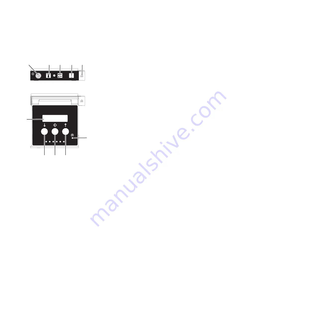
The top of the display, as shown in the following figure, shows

01 V=F

.

3.

Press the power button

(A)

, as shown in the following figure, on the control panel.

v

A

: Power-on button

– A constant light indicates full system power to the unit.
– A flashing light indicates standby power to the unit.
– There is approximately a 30-second transition period from the time the power-on button is

pressed to when the power LED goes from flashing to solid. During the transition period, the
LED might flash faster.

v

B

: Enclosure identify light

– A constant light indicates the identify state, which is used to identify a part.
– No light indicates that the system is operating normally.

v

C

: System information light

– No light indicates that the system is operating normally.
– Light on indicates that the system requires attention.

v

D

: Enclosure fault roll-up light

– A constant light indicates a fault in the enclosure.
– No light indicates that the system is operating normally.

v

E

: Eject button

v

F

: Function/Data display

v

G

: Pinhole reset button

v

H

: Decrement button

v

I

: Enter button

v

J

: Increment button

4.

Observe the following aspects after pressing the power button:

A

B

C

D

E

F

G

H

I

J

Front View

Top View

P8HB5500-1

Figure 46. Control panel

50

Power Systems: Installing the 5887 disk drive enclosure

Содержание 5887

Страница 1: ...Power Systems Installing the 5887 disk drive enclosure GI11 9909 02 ...

Страница 2: ......

Страница 3: ...Power Systems Installing the 5887 disk drive enclosure GI11 9909 02 ...

Страница 4: ... Notices manual G229 9054 and the IBM Environmental Notices and User Guide Z125 5823 This edition applies to IBM Power Systems servers that contain the POWER8 processor and to all associated models Copyright IBM Corporation 2014 2015 US Government Users Restricted Rights Use duplication or disclosure restricted by GSA ADP Schedule Contract with IBM Corp ...

Страница 5: ...ntrol panel 47 Stopping a system by using the ASMI 47 Stopping a system by using the HMC 48 Stopping a system by using the HMC Classic or HMC Enhanced interface 48 Stopping a system by using the HMC Enhanced Tech Preview Pre GA or HMC Enhanced interface 48 Stopping an IBM PowerKVM system 49 Starting the system or logical partition 49 Starting a system that is not managed by an HMC 49 Starting a sy...

Страница 6: ...ocations 66 Model 8246 L1T connector locations 66 Model 8246 L2S connector locations 66 Model 8246 L2T connector locations 67 Model 8248 L4T 8408 E8D or 9109 RMD connector locations 67 Model 9117 MMB or 9179 MHB connector locations 68 Model 9117 MMC or 9179 MHC connector locations 69 Model 9117 MMD or 9179 MHD connector locations 69 Notices 71 Privacy policy considerations 72 Trademarks 73 Electro...

Страница 7: ...uct The documentation contains the safety information in your national language with references to the U S English source Before using a U S English publication to install operate or service this product you must first become familiar with the related safety information documentation You should also refer to the safety information documentation any time you do not clearly understand any safety inf...

Страница 8: ... that will be attached to this product to properly wired outlets v When possible use one hand only to connect or disconnect signal cables v Never turn on any equipment when there is evidence of fire water or structural damage v Disconnect the attached power cords telecommunications systems networks and modems before you open the device covers unless instructed otherwise in the installation and con...

Страница 9: ...he customer to ensure that the outlet is correctly wired and grounded to prevent an electrical shock CAUTION v Do not install a unit in a rack where the internal rack ambient temperatures will exceed the manufacturer s recommended ambient temperature for all your rack mounted devices v Do not install a unit in a rack where the air flow is compromised Ensure that air flow is not blocked or reduced ...

Страница 10: ...ith your rack cabinet for the weight of a loaded rack cabinet v Verify that all door openings are at least 760 x 230 mm 30 x 80 in v Ensure that all devices shelves drawers doors and cables are secure v Ensure that the four leveling pads are raised to their highest position v Ensure that there is no stabilizer bracket installed on the rack cabinet during movement v Do not use a ramp inclined at mo...

Страница 11: ...ot to be used as shelves or work spaces L002 L003 or or 1 2 3 4 DANGER Multiple power cords The product might be equipped with multiple power cords To remove all hazardous voltages disconnect all power cords L003 L007 Safety notices ix ...

Страница 12: ...hazardous laser radiation There are no serviceable parts inside the device v Use of the controls or adjustments or performance of procedures other than those specified herein might result in hazardous radiation exposure C026 CAUTION Data processing environments can contain equipment transmitting on system links with laser modules that operate at greater than Class 1 power levels For this reason ne...

Страница 13: ...re the NEC National Electrical Code applies The intrabuilding ports of this equipment are suitable for connection to intrabuilding or unexposed wiring or cabling only The intrabuilding ports of this equipment must not be metallically connected to the interfaces that connect to the OSP outside plant or its wiring These interfaces are designed for use as intrabuilding interfaces only Type 2 or Type ...

Страница 14: ...xii Power Systems Installing the 5887 disk drive enclosure ...

Страница 15: ...all your 5887 disk drive enclosure Learn about the prerequisites for installing your 5887 disk drive enclosure and determine whether you can install the enclosure concurrently To prepare to set up your enclosure complete the following steps 1 Review the following information The SAS disk drive enclosure can hold up to 24 disk drives The enclosure can be split logically into one two or four indepen...

Страница 16: ... worldwide contacts website http http www ibm com planetwide Select your location to view the service and support contact information Determining and marking the location in the rack Learn how to determine where to install the disk drive enclosure into the rack Read the Rack safety notices http www ibm com support knowledgecenter POWER8 p8hbf racksafety htm To determine where to install the disk d...

Страница 17: ...ackaging and installing or replacing hardware touch an unpainted metal surface of the system for a minimum of 5 seconds 4 If necessary remove the filler panels to allow access to the inside of the rack enclosure where you plan to place the enclosure See Figure 1 5 If necessary open or remove the front and rear rack doors 6 Face the front of the rack and work from the left side to complete the foll...

Страница 18: ...er to yourself and to the unit ensure that you have the correct rails and fittings for your rack If your rack has square support flange holes or screw thread support flange holes ensure that the rails and fittings match the support flange holes that are used on your rack Do not install mismatched hardware by using washers or spacers If you do not have the correct rails and fittings for your rack c...

Страница 19: ...The support ledge A is at the bottom and points toward the center of the open space v The enclosure stop B points toward the rear of the rack 6 Locate the two marks that were made previously on the Electronic Industries Alliances EIA strips Figure 3 Installing the spring to the rail Figure 4 Opening the rail hinge bracket Installing the 5887 disk drive enclosure or setting up a preinstalled 5887 d...

Страница 20: ...unting holes The bottom of the rail support ledge appears slightly higher than the U mark on the rack flange 8 At the front of the rail close the front hinge bracket to secure the rail to the rack cabinet flange Figure 5 Mounting the rail on the rack 6 Power Systems Installing the 5887 disk drive enclosure ...

Страница 21: ...to the rack In addition to related safety information illustrations of the related hardware components are provided Important Two people are required to safely lift the enclosure Using fewer than two people to lift the enclosure can result in injury To install the disk drive enclosure into the rack complete the following steps 1 Ensure that you have the electrostatic discharge ESD wrist strap atta...

Страница 22: ... to lift the enclosure can result in injury 5 Slide the disk drive enclosure into the rack cabinet 6 Secure the front of the disk drive enclosure to the rack flanges with one M5 screw C in the bottom open holes in each bracket Figure 7 Removing the side covers Figure 8 Sliding the disk drive enclosure into the rack 8 Power Systems Installing the 5887 disk drive enclosure ...

Страница 23: ...f not attach it now 2 Remove the drive from the static protective package Attention Drives are fragile Handle with care 3 With the handle in the unlocked position support the bottom of the disk drive as you align it with the guide rails in the disk drive enclosure See Figure 10 on page 10 Figure 9 Securing the front of the disk drive enclosure to the rack Installing the 5887 disk drive enclosure o...

Страница 24: ...ts the following operating systems v AIX v IBM i v Linux v VIOS If you are planning to configure RAID arrays ensure that you have the minimum number of available disks for each RAID level RAID 0 Minimum of one drive per array RAID 5 Minimum of three drives per array RAID 6 Minimum of four drives per array RAID 10 Minimum of two drives per array Connecting the 5887 disk drive enclosure to your syst...

Страница 25: ...of the external SAS port on the system Later in this procedure you are instructed to install the external SAS cable to this system connector location 5 Determine the configuration that you will use to cable the SAS adapter to the 5887 disk drive enclosure The following list shows some of the common connections but not all possible connection options For more configuration options see Planning for ...

Страница 26: ... partition on page 47 Then continue with step 12 No Continue with step 9 9 Select from the following options v If you can unconfigure the SAS adapters go to step 10 v If you can not unconfigure the SAS adapters you will need to power off the SAS adapters Go to step 11 10 To unconfigure the SAS adapters complete these steps a Unconfigure the SAS adapters b Ensure that you have the electrostatic dis...

Страница 27: ...wo SAS adapter pairs go to step 18 on page 17 v To complete a mode 4 connection of one 5887 disk drive enclosure by using X cables to four independent SAS adapters go to step 19 on page 18 If your SAS configuration requirements are not supported by any of these options go to step 20 on page 20 13 Perform the mode 1 connection of one enclosure A by using a YO cable B to a single SAS adapter C See F...

Страница 28: ... adapter pair C has access to the other adapter and to all 24 drive bays v If 6 Gb SAS adapters are being used they must be cabled by using 6 Gb SAS cables v For SAS adapter pairs you can attach the cables to any adapter port when you use the same port in both adapters Figure 13 Mode 1 connection of two 5887 disk drive enclosures by using YO cables to a single SAS adapter 14 Power Systems Installi...

Страница 29: ... C has access to the other adapter and to all 48 drive bays v If 6 Gb SAS adapters are being used they must be cabled by using 6 Gb SAS cables v For SAS adapter pairs you can attach the cables to any adapter port when you use the same port in both adapters Figure 14 Mode 1 connection of one 5887 disk drive enclosure by using YO cables to a SAS adapter pair Installing the 5887 disk drive enclosure ...

Страница 30: ...s v Independent SAS adapter 1 C does not have access to the other independent adapter and has access only to drive bays D1 D12 v Independent SAS adapter 2 D does not have access to the other independent adapter and has access only to drive bays D13 D24 Figure 15 Mode 1 connection of two 5887 disk drive enclosures by using YO cables to a SAS adapter pair 16 Power Systems Installing the 5887 disk dr...

Страница 31: ... Each adapter in the SAS adapter pair 2 D has access to the other adapter and to drive bays D13 D24 v If 6 Gb SAS adapters are being used they must be cabled by using 6 Gb SAS cables v For SAS adapter pairs you can attach the cables to any adapter port when you use the same port in both adapters Figure 16 Mode 2 connection of one 5887 disk drive enclosure by using YO cables to two independent SAS ...

Страница 32: ...er 2 D contains a label with the P2 identifier G This adapter does not have access to any other independent adapter and has access only to drive bays D7 D12 v The cable that plugs into independent SAS adapter 3 E contains a label with the P1 identifier G This adapter does not have access to any other independent adapter and has access only to drive bays D13 D18 v The cable that plugs into independ...

Страница 33: ...disk drive enclosure by using X cables to four independent SAS adapters Figure 19 Labels for SAS adapter cables that show P1 and P2 identifiers Installing the 5887 disk drive enclosure or setting up a preinstalled 5887 disk drive enclosure 19 ...

Страница 34: ...s 1 Ensure that you have the electrostatic discharge ESD wrist strap attached If not attach it now 2 If your installation requirements included the removal of the SAS cables from the ESMs review the labeling that you completed and reinstall the cables Note Do not apply power until instructed to do so 3 Route the power cords through the power cord retention brackets D for strain relief as shown in ...

Страница 35: ...ate the cover down until it snaps into place Make sure that the inside surface of the cover is flush with the chassis 8 Connect the other end of the power cables to the power distribution units PDUs Figure 21 Connecting the power cords Figure 22 Attaching the side covers Installing the 5887 disk drive enclosure or setting up a preinstalled 5887 disk drive enclosure 21 ...

Страница 36: ...closure see Verifying the installed part http www ibm com support knowledgecenter POWER8 p8haj pxhaj_hsmverify htm 3 You have completed the steps to install your 5887 disk drive enclosure If you were directed here from another procedure return to that procedure now Setting up a preinstalled 5887 disk drive enclosure Learn about the steps to set up a preinstalled 5887 disk drive enclosure Preparing...

Страница 37: ...m damaging your hardware v When using an ESD wrist strap follow all electrical safety procedures An ESD wrist strap is used for static control It does not increase or decrease your risk of receiving electric shock when using or working on electrical equipment v If you do not have an ESD wrist strap just prior to removing the product from ESD packaging and installing or replacing hardware touch an ...

Страница 38: ... Loosen the two thumbscrews A on the small front brackets below the ESM units Remove the brackets by lifting them up and away from the ESM units Figure 23 Removing the power supply cords from their shipping position 24 Power Systems Installing the 5887 disk drive enclosure ...

Страница 39: ...e of the rack frame Then remove the screw that attaches the bracket to right flange Note Keep the screws that you remove for later in the procedure Figure 24 Removing the small front brackets Installing the 5887 disk drive enclosure or setting up a preinstalled 5887 disk drive enclosure 25 ...

Страница 40: ...ds to remove it from the side rails Tip Save all of the brackets that you remove for future reinstallation and for shipping of the enclosure that might be required Figure 25 Removing the screws from the bracket and rack flanges 26 Power Systems Installing the 5887 disk drive enclosure ...

Страница 41: ...te the following steps a Moving one ESM at a time slide the unit approximately 75 mm 3 in toward the chassis b For one ESM at a time place your forefingers under the release levers and pinch the terracotta lever tips Release the levers and swing them into their fully open position Figure 26 Removing the shipping bracket Installing the 5887 disk drive enclosure or setting up a preinstalled 5887 dis...

Страница 42: ... Moving one ESM at a time slide the unit into the chassis until it stops Figure 27 Opening the ESM release levers Figure 28 Docking the ESM units 28 Power Systems Installing the 5887 disk drive enclosure ...

Страница 43: ... and latched position 5 To dock and secure the power supplies complete the following steps a Moving one power supply at a time slide the unit approximately 75 mm 3 in away from the chassis Figure 29 Closing the ESM release levers Installing the 5887 disk drive enclosure or setting up a preinstalled 5887 disk drive enclosure 29 ...

Страница 44: ...atch beside the unit handle and your fingertips on the handle In one motion squeeze the release latch to the right and swing the handle down into its fully open position Figure 30 Sliding the power supplies toward the chassis 30 Power Systems Installing the 5887 disk drive enclosure ...

Страница 45: ...me slide the unit into the chassis until it stops Figure 31 Opening the power supply release handle Figure 32 Docking the power supplies Installing the 5887 disk drive enclosure or setting up a preinstalled 5887 disk drive enclosure 31 ...

Страница 46: ...ing steps 1 Ensure that you have the electrostatic discharge ESD wrist strap attached If not attach it now 2 Remove the drive from the static protective package Attention Drives are fragile Handle with care 3 With the handle in the unlocked position support the bottom of the disk drive as you align it with the guide rails in the disk drive enclosure For an example see Figure 34 on page 33 Figure 3...

Страница 47: ...systems v AIX v IBM i v Linux v VIOS If you are planning to configure RAID arrays ensure that you have the minimum number of available disks for each RAID level RAID 0 Minimum of one drive per array RAID 5 Minimum of three drives per array RAID 6 Minimum of four drives per array RAID 10 Minimum of two drives per array Connecting the preinstalled 5887 disk drive enclosure to your system Learn how t...

Страница 48: ... record the location of the external SAS port on the system Later in this procedure you are instructed to install the external SAS cable to this system connector location 5 Determine the configuration that you will use to cable the SAS adapter to the 5887 disk drive enclosure The following list shows some of the common connections but not all possible connection options For more configuration opti...

Страница 49: ...inue with step 9 9 Select from the following options v If you can unconfigure the SAS adapters go to step 10 v If you can not unconfigure the SAS adapters you will need to power off the SAS adapters Go to step 11 10 To unconfigure the SAS adapters complete these steps a Unconfigure the SAS adapters b Ensure that you have the electrostatic discharge ESD wrist strap attached If not attach it now c C...

Страница 50: ...e enclosure by using X cables to two SAS adapter pairs go to step 18 on page 40 v To complete a mode 4 connection of one 5887 disk drive enclosure by using X cables to four independent SAS adapters go to step 19 on page 41 If your SAS configuration requirements are not supported by any of these options go to step 20 on page 43 13 Perform the mode 1 connection of one enclosure A by using a YO cable...

Страница 51: ...es v Each adapter in the SAS adapter pair C has access to the other adapter and to all 24 drive bays v If 6 Gb SAS adapters are being used they must be cabled by using 6 Gb SAS cables v For SAS adapter pairs you can attach the cables to any adapter port when you use the same port in both adapters Figure 37 Mode 1 connection of two 5887 disk drive enclosures by using YO cables to a single SAS adapt...

Страница 52: ... v Each adapter in the SAS adapter pair C has access to the other adapter and to all 48 drive bays v If 6 Gb SAS adapters are being used they must be cabled by using 6 Gb SAS cables v For SAS adapter pairs you can attach the cables to any adapter port when you use the same port in both adapters Figure 38 Mode 1 connection of one 5887 disk drive enclosure by using YO cables to a SAS adapter pair 38...

Страница 53: ... Independent SAS adapter 1 C does not have access to the other independent adapter and has access only to drive bays D1 D12 v Independent SAS adapter 2 D does not have access to the other independent adapter and has access only to drive bays D13 D24 Figure 39 Mode 1 connection of two 5887 disk drive enclosures by using YO cables to a SAS adapter pair Installing the 5887 disk drive enclosure or set...

Страница 54: ...ther adapter and to drive bays D1 D12 v Each adapter in the SAS adapter pair 2 D has access to the other adapter and to drive bays D13 D24 v If 6 Gb SAS adapters are being used they must be cabled by using 6 Gb SAS cables v For SAS adapter pairs you can attach the cables to any adapter port when you use the same port in both adapters Figure 40 Mode 2 connection of one 5887 disk drive enclosure by ...

Страница 55: ...m the mode 4 connection of one enclosure A by using X cables B to four independent SAS adapters See Figure 42 on page 42 Figure 41 Mode 2 connection of one 5887 disk drive enclosure by using X cables to two SAS adapter pairs Installing the 5887 disk drive enclosure or setting up a preinstalled 5887 disk drive enclosure 41 ...

Страница 56: ...adapter and has access only to drive bays D7 D12 v The cable that plugs into independent SAS adapter 3 E contains a label with the P1 identifier G This adapter does not have access to any other independent adapter and has access only to drive bays D13 D18 v The cable that plugs into independent SAS adapter 4 F contains a label with the P2 identifier G This adapter does not have access to any other...

Страница 57: ...ostatic discharge ESD wrist strap attached If not attach it now 2 If your installation requirements included the removal of the SAS cables from the ESMs review the labeling that you completed and reinstall the cables Note Do not apply power until instructed to do so 3 Reinstall the left cover A which contains the service indicators and the right cover B 4 Fit the slot on the top of the cover over ...

Страница 58: ...rocess To complete the installation process complete the following steps 1 To learn how to add the disk drives to the operating system see the following information v To configure a disk drive or SSD for use by AIX see Configuring a disk drive or solid state drive for use in an AIX system or AIX logical partition http www ibm com support knowledgecenter POWER8 p8hal pxhal_configdrive_aix htm v To ...

Страница 59: ... To verify that the system or logical partition recognizes the disk drive enclosure see Verifying the installed part http www ibm com support knowledgecenter POWER8 p8haj pxhaj_hsmverify htm 3 You have completed the steps to install your 5887 disk drive enclosure If you were directed here from another procedure return to that procedure now Installing the 5887 disk drive enclosure or setting up a p...

Страница 60: ...46 Power Systems Installing the 5887 disk drive enclosure ...

Страница 61: ...tem to complete another task If your system is not managed by the Hardware Management Console HMC use these instructions to stop the system by using the power button The following procedure describes how to stop a system that is not managed by the HMC 1 Log in to the host partition as a user with the authority to run the shutdown or pwrdwnsys Power Down System command 2 At the command line enter o...

Страница 62: ...system you must be a member of one of the following roles v Super administrator v Service representative v Operator v Product engineer Note If you are a product engineer verify that the customer has shut down all active partitions and has powered off the managed system Continue with the procedure only after the status of the server changes to Power Off Stopping a system by using the HMC Classic or...

Страница 63: ...shutdown domain ID Note Type virsh list to verify whether all the guests are powered off If any guest is not powered off type virsh destroy domain name or type virsh destroy domain ID to power off the guest 3 Run the ipmitool I lanplus H FSP IP P ipmipassword chassis power off command from a remote system Starting the system or logical partition Learn how to start a system or logical partition aft...

Страница 64: ...ght indicates the identify state which is used to identify a part No light indicates that the system is operating normally v C System information light No light indicates that the system is operating normally Light on indicates that the system requires attention v D Enclosure fault roll up light A constant light indicates a fault in the enclosure No light indicates that the system is operating nor...

Страница 65: ...and the power cables are connected to a power source Starting a system or logical partition by using the HMC Classic or HMC Enhanced interface Learn how to start a system or logical partition by using the HMC Classic or HMC Enhanced interface To start the system by using the HMC Classic or HMC Enhanced interface complete the following steps 1 Verify that the logical partition start policy is set t...

Страница 66: ...titions that you want to activate e In the content pane click Actions Activate f Click OK 4 To verify that the logical partition start policy is set to User Initiated complete the following steps a In the navigation area click the Resources icon and then click All Systems b Click the system name to view details c In the navigation area click Properties Other Properties d Click the Power On Paramet...

Страница 67: ...support knowledgecenter POWER8 p8ecs p8ecs_emx0_loccodes htm Connector locations for POWER8 servers Learn about connector locations for POWER8 servers Connector locations for the 8247 21L 8247 22L and 8284 22A systems Learn about connector locations for the 8247 21L 8247 22L and 8284 22A systems The expanded function 8247 21L 8247 22L and 8284 22A servers provide cable connector locations via a SA...

Страница 68: ...he 8286 41A server provides cable connector locations via a SAS port for disk drive enclosures Figure 49 Connector locations for the expanded function 8247 21L 8247 22L and 8284 22A systems Figure 50 Connector locations for the rack mounted 8286 41A expanded function system 54 Power Systems Installing the 5887 disk drive enclosure ...

Страница 69: ...ed models The 8286 42A expanded function server provides cable connector locations via a SAS port for disk drive enclosures Figure 51 Connector locations for the stand alone 8286 41A expanded function system Figure 52 Connector locations for the 8286 42A expanded function system Reference information 55 ...

Страница 70: ...cable ports P1 C5 T1 and P1 C5 T2 for the PCIe3 expansion drawer Connector locations for the 9119 MHE and 9119 MME systems Learn about connector locations for the 9119 MHE and 9119 MME systems The 9119 MHE and 9119 MME servers provide cable connector locations for the PCIe Gen3 I O expansion drawer Figure 53 Connector locations for an 8408 E8E system 56 Power Systems Installing the 5887 disk drive...

Страница 71: ...1 P1 T2 P1 T3 P1 T4 P1 T5 P1 T6 P1 T8 P1 C10 P1 C10 T1 P1 P1 C12 C10 T2 P1 C9 P1 C9 T1 P1 C9 T2 P1 C11 P1 T7 P1 C5 P1 C6 P1 C7 P1 C8 P1 C5 C1 P1 C6 C1 P1 C7 C1 P1 C8 C1 P1 C1 P1 C1 C1 P1 C2 P1 C3 P1 C4 P1 C2 C1 P1 C3 C1 P1 C4 C1 P8ECS804 1 Figure 54 Connector locations for the 9119 MHE and 9119 MME systems Figure 55 Model 8202 E4B connector locations on a rack mounted model Reference information 5...

Страница 72: ...oth 12X DDR and PCIe cable ports The server contains a serial attached SCSI SAS port v Support for disk drive enclosures as shown in the following figure is as follows The server contains a SAS port v Support for PCIe storage enclosures as shown in the following figure is as follows The card installed in the C1 slot can contain two PCIe cable ports However the C1 slot cannot provide both PCIe and ...

Страница 73: ...rial attached SCSI SAS port v Support for disk drive enclosures as shown in the following figure is as follows The server contains a SAS port v Support for PCIe storage enclosures as shown in the following figure is as follows The card installed in the C1 slot can contain two PCIe cable ports However the C1 slot cannot provide both PCIe and 12X DDR cable ports The server contains a SAS port Figure...

Страница 74: ...r the following enclosures v Support for expansion units as shown in the following figure is as follows The card installed in the C1 slot can contain two 12X double data rate DDR cable ports However the C1 slot cannot provide both 12X DDR and PCIe cable ports Figure 59 Model 8205 E6B connector locations on a rack mounted model Figure 60 Model 8205 E6B connector locations on a stand alone model 60 ...

Страница 75: ... following enclosures v Support for expansion units as shown in the following figure is as follows The card installed in the C1 slot can contain two 12X double data rate DDR cable ports However the C1 slot cannot provide both 12X DDR and PCIe cable ports The card installed in the C8 slot can contain two 12X DDR cable ports However the C8 slot cannot provide both 12X DDR and PCIe cable ports The po...

Страница 76: ...E1D connector locations Learn about connector locations The 8231 E1D or 8268 E1D servers provides cable connector locations for the following enclosures v Support for disk drive enclosures as shown in the following figure is as follows The server contains a serial attached SCSI SAS port v Support for PCIe storage enclosures as shown in the following figure is as follows The card installed in the C...

Страница 77: ...v Support for expansion units as shown in the following figure is as follows The C1 slot must contain the system power control network SPCN card and the C8 slot must contain the card with two 12X double data rate DDR cable ports Note Installing the 12X DDR cable ports at this location causes both the C8 and C6 slot space to be occupied The server cannot support both 12X DDR cable ports and PCIe ca...

Страница 78: ...ing figure is as follows The C1 slot must contain the system power control network SPCN card and the C8 slot must contain the card with two 12X double data rate DDR cable ports Note Installing the 12X DDR cable ports at this location causes both the C8 and C6 slot space to be occupied The server cannot support both 12X DDR cable ports and PCIe cable ports at the same time The server contains a ser...

Страница 79: ...not support both PCIe cable ports and 12X DDR cable ports at the same time The server contains a SAS port Model 8233 E8B connector locations Learn about connector locations on rack mounted models Figure 68 Model 8231 E2D connections for expansion units and disk drive enclosures Figure 69 Model 8231 E2D connections for PCIe storage enclosures Figure 70 Model 8233 E8B connector locations on a rack m...

Страница 80: ...tions Learn about connector locations Model 8246 L2S connector locations Learn about connector locations Figure 71 Model 8246 L1S connector locations Figure 72 Model 8246 L1T connector locations Figure 73 Model 8246 L2S connector locations 66 Power Systems Installing the 5887 disk drive enclosure ...

Страница 81: ...e ports The card installed in the C3 slot can contain two 12X DDR cable ports However the C3 slot cannot provide both 12X DDR and PCIe cable ports v Support for disk drive enclosures as shown in the following figure is as follows The server contains a SAS port v Support for PCIe storage enclosures as shown in the following figure is as follows The card installed in the C2 slot can contain two PCIe...

Страница 82: ...ctor locations Figure 75 Model 8248 L4T 8408 E8D or 9109 RMD connector locations for expansion units disk drive enclosures and PCIe storage enclosures Figure 76 Model 9117 MMB or 9179 MHB connector locations 68 Power Systems Installing the 5887 disk drive enclosure ...

Страница 83: ...he card installed in the C3 slot can contain two 12X DDR cable ports However the C3 slot cannot provide both 12X DDR and PCIe cable ports v Support for disk drive enclosures as shown in the following figure is as follows The server contains a SAS port v Support for PCIe storage enclosures as shown in the following figure is as follows The card installed in the C2 slot can contain two PCIe cable po...

Страница 84: ...Figure 78 Model 9117 MMD or 9179 MHD connector locations for expansion units disk drive enclosures and PCIe storage enclosures 70 Power Systems Installing the 5887 disk drive enclosure ...

Страница 85: ...D WARRANTIES OF NON INFRINGEMENT MERCHANTABILITY OR FITNESS FOR A PARTICULAR PURPOSE Some states do not allow disclaimer of express or implied warranties in certain transactions therefore this statement may not apply to you This information could include technical inaccuracies or typographical errors Changes are periodically made to the information herein these changes will be incorporated in new ...

Страница 86: ...erations performed and data saved or transmitted by the system at or near the time of the outage or failure In addition users must establish procedures to ensure that there is independent data verification before relying on such data in sensitive or critical operations Users should periodically check IBM s support websites for updated information and fixes applicable to the system and related soft...

Страница 87: ...e limits are designed to provide reasonable protection against harmful interference when the equipment is operated in a commercial environment This equipment generates uses and can radiate radio frequency energy and if not installed and used in accordance with the instruction manual may cause harmful interference to radio communications Operation of this equipment in a residential area is likely t...

Страница 88: ...3 email halloibm de ibm com Warning This is a Class A product In a domestic environment this product may cause radio interference in which case the user may be required to take adequate measures VCCI Statement Japan The following is a summary of the VCCI Japanese statement in the box above This is a Class A product based on the standard of the VCCI Council If this equipment is used in a domestic e...

Страница 89: ... need to perform practical action Electromagnetic Interference EMI Statement Taiwan The following is a summary of the EMI Taiwan statement above Warning This is a Class A product In a domestic environment this product may cause radio interference in which case the user will be required to take adequate measures IBM Taiwan Contact Information Electromagnetic Interference EMI Statement Korea Notices...

Страница 90: ...l kann vom Betreiber verlangt werden angemessene Maßnahmen zu ergreifen und dafür aufzukommen Deutschland Einhaltung des Gesetzes über die elektromagnetische Verträglichkeit von Geräten Dieses Produkt entspricht dem Gesetz über die elektromagnetische Verträglichkeit von Geräten EMVG Dies ist die Umsetzung der EU Richtlinie 2004 108 EG in der Bundesrepublik Deutschland Zulassungsbescheinigung laut ...

Страница 91: ... following measures v Reorient or relocate the receiving antenna v Increase the separation between the equipment and receiver v Connect the equipment into an outlet on a circuit different from that to which the receiver is connected v Consult an IBM authorized dealer or service representative for help Properly shielded and grounded cables and connectors must be used in order to meet FCC emission l...

Страница 92: ...imits for Class B equipment were derived for typical residential environments to provide reasonable protection against interference with licensed communication equipment European Community contact IBM Deutschland GmbH Technical Regulations Department M372 IBM Allee 1 71139 Ehningen Germany Tele 49 0 800 225 5423 or 49 0 180 331 3233 email halloibm de ibm com VCCI Statement Japan Japanese Electroni...

Страница 93: ...hland Einhaltung des Gesetzes über die elektromagnetische Verträglichkeit von Geräten Dieses Produkt entspricht dem Gesetz über die elektromagnetische Verträglichkeit von Geräten EMVG Dies ist die Umsetzung der EU Richtlinie 2004 108 EG in der Bundesrepublik Deutschland Zulassungsbescheinigung laut dem Deutschen Gesetz über die elektromagnetische Verträglichkeit von Geräten EMVG bzw der EMC EG Ric...

Страница 94: ...out the express consent of IBM Rights Except as expressly granted in this permission no other permissions licenses or rights are granted either express or implied to the publications or any information data software or other intellectual property contained therein IBM reserves the right to withdraw the permissions granted herein whenever in its discretion the use of the publications is detrimental...

Страница 95: ......

Страница 96: ... Part Number 00RW813 Printed in USA GI11 9909 02 1P P N 00RW813 ...

Отзывы: