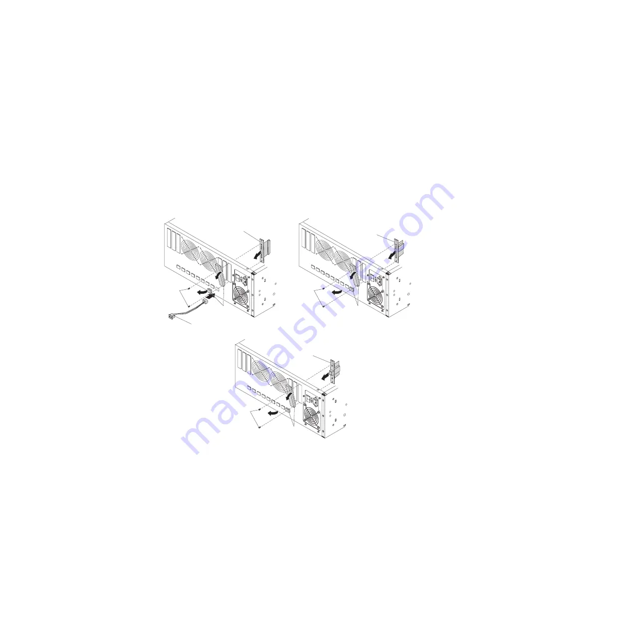
6.
Install
the
signal
connectors:
a.
Remove
the
cover
plates
from
the
rear
of
the
enclosure.
b.
For
a
SCSI
drive,
use
the
tip
of
a
pen
or
a
straightened
paper
clip
to
set
the
ID
on
the
SCSI
ID
connector.
The
rear
of
the
enclosure
is
marked
“0”
through
“8”,
just
above
the
openings
for
the
SCSI
ID
connectors.
To
help
avoid
confusion,
set
the
SCSI
ID
on
the
connector
to
match
the
marking
on
the
rear
of
the
enclosure.
c.
Orient
the
connector
with
the
“R”
marking
facing
up;
then,
insert
it
into
the
opening
and
press
it
firmly
in
place.
d.
Insert
the
signal
connector
into
the
opening
in
the
enclosure;
then,
insert
and
tighten
the
screws
to
secure
the
connector.
SCSI
signal
connector
screws
SCSI
signal
connector
SCSI ID connector
Connector
plugs
SCSI
SAS
signal
connector
screws
SAS signal
connector
Connector
plugs
SAS or SATA
USB
signal
connector
screws
USB signal
connector
Connector
plugs
USB
Chapter
2.
Installing
the
tape
enclosure
13
Содержание 4 U
Страница 1: ...IBM 4 U Rack Mount Tape Enclosure Installation Guide...
Страница 2: ......
Страница 3: ...IBM 4 U Rack Mount Tape Enclosure Installation Guide...
Страница 8: ...vi IBM 4 U Rack Mount Tape Enclosure Installation Guide...
Страница 14: ...6 IBM 4 U Rack Mount Tape Enclosure Installation Guide...
Страница 28: ...20 IBM 4 U Rack Mount Tape Enclosure Installation Guide...
Страница 55: ......
Страница 56: ...Part Number 44E8015 Printed in USA 1P P N 44E8015...


