background image

 8

IBM® xSeries 220: Installation Guide


Содержание 220

Страница 1: ...he server and options Start the server Install the server in the rack if required Did the server start correctly Yes No Use ServerGuide to setup and configure hardware Did configuration complete Use ServerGuide to install operating system Use ServerGuide to install applications such as IBM systems management software and IBM ServeRAID programs System is ready to use Go to the Server Support flow c...

Страница 2: ...ubleshooting information provided with your server to determine the cause of the problem and the action to take Flash the latest levels of BIOS service processor diagnostics and RAID code You can download this code at http www ibm com pc support No No Yes Yes Yes Check all cables for loose connections and verify that all optional devices you installed are on the ServerProven list You can view the ...

Страница 3: ...IBM IBM xSeries 220 Installation Guide SC06 P459 80 ...

Страница 4: ...nformation in Appendix A Product warranties and notices on page 49 First Edition October 2000 Copyright International Business Machines Corporation 2000 All rights reserved US Government Users Restricted Rights Use duplication or disclosure restricted by GSA ADP Schedule Contract with IBM Corp ...

Страница 5: ...ower controls and indicators 35 Turning on the server 35 Turning off the server 36 Server controls and indicators 37 Chapter 4 Configuring your server 39 Using the ServerGuide CDs 39 Chapter 5 Solving problems 41 Diagnostic tools overview 41 POST beep code descriptions 42 POST error messages 43 ServerGuide startup problems 44 Troubleshooting chart 45 Appendix A Product warranties and notices 49 Wa...

Страница 6: ...iv IBM xSeries 220 Installation Guide ...

Страница 7: ...rjanen ennen kuin asennat tämän tuotteen Avant de procéder à l installation de ce produit lisez le manuel Safety Information Vor Beginn der Installation die Broschüre mit Sicherheitshinweisen lesen Prima di installare questo prodotto leggere l opuscolo contenente le informazioni sulla sicurezza Pred instalací tohoto produktu si prectete prírucku bezpecnostních instrukcí Przed zainstalowaniem tego ...

Страница 8: ...o Informações sobre Segurança Antes de instalar este producto lea la Información de Seguridad Läs säkerhetsinformationen innan du installerar den här produkten Перед установкой продукта прочтите брошюру по технике безопасности Safety Information Pred inštaláciou tohto produktu si pre ítajte Informa nú brožúrku o bezpe nosti Preden namestite ta izdelek preberite knjižico Varnostne informacije Insta...

Страница 9: ...ny equipment when there is evidence of fire water or structural damage Disconnect the attached power cords telecommunications systems networks and modems before you open the device covers unless instructed otherwise in the installation and configuration procedures Connect and disconnect cables as described in the following table when installing moving or opening covers on this product or attached ...

Страница 10: ...required by local ordinances or regulations Statement 3 CAUTION When laser products such as CD ROMs DVD drives fiber optic devices or transmitters are installed note the following Do not remove the covers Removing the covers of the laser product could result in exposure to hazardous laser radiation There are no serviceable parts inside the device Use of controls or adjustments or performance of pr...

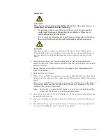
Страница 11: ...TION The power control button on the device and the power switch on the power supply do not turn off the electrical current supplied to the device The device also might have more than one power cord To remove all electrical current from the device ensure that all power cords are disconnected from the power source 1 2 ...

Страница 12: ...x IBM xSeries 220 Installation Guide ...

Страница 13: ... circuitry Do not leave the device where others can handle and possibly damage the device While the device is still in its anti static package touch it to an unpainted metal part of the system unit for at least two seconds This drains static electricity from the package and from your body Remove the device from its package and install it directly into your system unit without setting it down If it...

Страница 14: ...xii IBM xSeries 220 Installation Guide ...

Страница 15: ...all your server in a rack refer to the Tower to Rack Conversion Kit manual and the Rack Installation Instructions that are provided with your optional rack hardware for complete installation and removal instructions The server serial number is located on labels on the rear of the server and on the front of the server below the bezel Note Your server keys cannot be duplicated by locksmiths If you l...

Страница 16: ...ory Size Height 470 mm 18 5 in Depth 508 mm 20 in Width 165 mm 6 5 in Weight approximately 19 5 Kg 43 lb when fully configured or 15 9 Kg 35 lb minimum Integrated functions Ultra160 SCSI low voltage differential LVD controller One 10BASE T 100BASE TX Intel Ethernet controller on the system board Two serial ports Parallel port Two Universal Serial Bus USB ports Keyboard port Mouse port IDE controll...

Страница 17: ...he description of a potentially hazardous procedure step or situation Danger These notices indicate situations that can be potentially lethal or extremely hazardous to you A danger notice is placed just before the description of a potentially lethal or extremely hazardous procedure step or situation Major components of the xSeries 220 server The orange color on components and labels in your server...

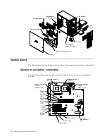
Страница 18: ... for user installable options Rear adapter retaining bracket Front adapter support bracket Drive cage Microprocessor Memory modules Cover Support bracket assembly EMC shields Filler panels Microprocessor 2 U11 Microprocessor 1 U12 Voltage regulator module VRM 2 J12 Voltage regulator module VRM 1 J42 DIMM 1 J19 DIMM 2 J21 DIMM 3 J23 DIMM 4 J26 PCI 1 J29 PCI 2 J31 PCI 3 J35 PCI 4 J39 PCI 5 J40 Batte...

Страница 19: ... the service processor System board internal cable connectors The following illustration identifies system board connectors for internal cables System board external port connectors The following illustration identifies system board connectors for external devices Microprocessor fan 2 J2 Microprocessor fan 1 J3 Fan 3 power J22 not used IDE J30 Diskette drive J27 SCSI channel J41 Fan 2 power J18 Fa...

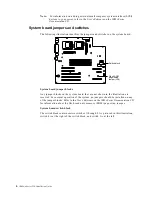
Страница 20: ... Any jumper blocks on the system board that are not shown in the illustration are reserved For normal operation of the system no jumpers should be installed on any of the jumper blocks Refer to the User s Reference on the IBM xSeries Documentation CD for information about the flash read only memory ROM page swap jumper System board switch block The switch block contains microswitches 1 through 8 A...

Страница 21: ...l switches in the switch block Switch number Switch description 8 Power on password override switch When toggled to the side that is opposite the default position bypasses the power on password if one is set 7 Reserved 6 Reserved 5 Force power on 4 Reserved 3 Reserved 2 Reserved 1 Reserved Table 2 Switches 1 through 8 ...

Страница 22: ...8 IBM xSeries 220 Installation Guide ...

Страница 23: ...utlets for your server monitor and any other options that you intend to install Back up all important data before you make changes to disk drives Have a small flat blade screwdriver available For a list of supported options for your server refer to http www ibm com pc compat on the World Wide Web System reliability considerations To help ensure proper cooling and system reliability make sure that ...

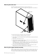
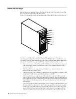
Страница 24: ... then slide the cover toward the rear of the server and remove it Attention For proper cooling and airflow replace the cover before turning on the server Operating the server for extended periods of time over 30 minutes with the cover removed might damage server components 5 For a tower model rotate the stabilizing feet on the bottom of the server and place the server on its side to install or rem...

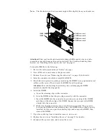
Страница 25: ...d remove the voltage regulator module VRM from connector J42 See System board option connectors on page 4 for connector locations Note Remember to reinstall this VRM after you reinstall the support bracket assembly 6 Disconnect the fan cable connector J10 from the system board See System board internal cable connectors on page 5 for connector locations Note Remember to reconnect this cable after y...

Страница 26: ...ntroller When you install a video adapter the server BIOS automatically disables the integrated video controller The following illustration shows the location of the 33 MHz PCI expansion slots Note The illustrations in this document might differ slightly from your hardware PCI slot 1 32 bit 33 MHz J29 PCI slot 2 32 bit 33 MHz J31 PCI slot 3 64 bit 33 MHz J35 PCI slot 4 64 bit 33 MHz J39 PCI slot 5...

Страница 27: ...red to as bus 0 PCI bus B is sometimes referred to as bus 1 The system scans PCI slots 1 through 5 to assign system resources then the system starts boots the PCI devices in the following order PCI slots 1 and 2 system board SCSI devices and then PCI slots 3 through 5 If you plan to use the Wake on LAN WOL function in the server you must install a Wake on LAN enabled network interface card NIC ada...

Страница 28: ...support bracket assembly from the server see Removing the support bracket assembly on page 10 Store the cover and the support bracket assembly in a safe place 5 Determine which expansion slot you will use for the adapter Note Check the instructions that come with the adapter for any requirements or restrictions 6 Remove the rear adapter retaining bracket from the server If you are installing a ful...

Страница 29: ...rd connector before you apply power Incomplete insertion might cause damage to the system board or the adapter c When the adapter is fully seated release the front adapter support bracket by pushing inward on the latch Make sure that the front adapter support bracket holds the adapter securely in place d If you opened the front adapter support bracket rotate it to the closed locked position then r...

Страница 30: ... in DIMM2 J21 and the fourth in DIMM4 J26 See the following illustration for memory connector locations 2 Your xSeries 220 server supports 128 MB 256 MB 512MB and 1GB DIMMs Your server supports a maximum of 4GB of system memory See the ServerProven list at http www ibm com pc us compat for a list of memory modules for use with your server 3 Installing or removing DIMMs changes the configuration in...

Страница 31: ...he package Attention To avoid breaking the retaining clips or damaging the DIMM connectors handle the clips gently 6 Install the DIMM a Open the retaining clips on the connector b Turn the DIMM so that the pins align correctly with the connector c Insert the DIMM into the connector by pressing on one edge of the DIMM and then on the other edge of the DIMM Ensure that you press the DIMM straight in...

Страница 32: ...eries 220 server supports five 3 5 inch drives however the server supports only one diskette drive The diskette drive uses 1 MB and 2 MB diskettes For optimum use format 1 MB diskettes to 720 KB and format 2 MB diskettes to 1 44 MB The xSeries 220 server supports two 5 25 inch drives and four SCSI hard disk drives The server does not support IDE hard disk drives Some models support hot swap hard d...

Страница 33: ...he filler panel from the bay in case you later remove the drive and do not replace it with another Preinstallation steps all bays Before you install drives in your server verify that you have all the cables and any other equipment specified in the documentation that comes with the drive You might also need to perform certain preinstallation activities Some of the steps are required only during the...

Страница 34: ...d peripheral devices then remove the side cover see Removing the side cover on page 10 for details 3 Insert a screwdriver into the slot on the right side of the filler panel and remove the filler panel from the server 4 Insert a screwdriver into the slots on the front of the EMC shield and remove the EMC shield from the bay 5 If the drive is a laser product observe the following safety precaution ...

Страница 35: ...he microprocessors 10 Connect a power cable to the back of the drive The connectors are keyed and can be inserted only one way 11 If you are installing another drive do so now Otherwise continue with the next step 12 If you have other options to install or remove do so now otherwise replace the cover see Installing the cover on page 31 for details Statement 3 CAUTION When laser products such as CD...

Страница 36: ... static sensitive devices on page xi To maintain proper system cooling do not operate the server for more than two minutes without either a drive or a filler panel installed in each bay Notes 1 The illustrations in this document might differ slightly from your hardware 2 If your server has a redundant array of independent disks RAID adapter installed refer to the information provided with the RAID...

Страница 37: ...l or remove do so now otherwise replace the support bracket assembly and the side cover see Installing the cover on page 31 for details Note If your server is a hot swap model reinstall the VRM in connector J42 after you reinstall the support bracket assembly Installing a hot swap hard disk drive in bay 5 6 or 7 If you purchased a hot swap model your server contains hardware that you can use to re...

Страница 38: ...ons in this document might differ slightly from your hardware Note The hard disk drive activity light and hard disk drive status light on the backplane match the hard disk drive activity light and hard disk drive status light on the hot swap drive The following illustration shows the rear connectors on the hot swap drive backplane as viewed from the rear of the server The following illustration sh...

Страница 39: ... filler panel and pulling it away from the server 4 Install the hard disk drive in the hot swap bay a Ensure that the tray handle is open that is perpendicular to the drive b Align the drive tray assembly with the guide rails in the bay c Gently push the drive tray assembly into the bay until the drive stops d Push the tray handle to the closed locked position e Check the hard disk drive status li...

Страница 40: ...at http www ibm com pc compat for a list of microprocessors for use with your server When you handle electrostatic discharge ESD sensitive devices take precautions to avoid damage from static electricity For details on handling these devices see Handling static sensitive devices on page xi To install an additional microprocessor do the following 1 Review the safety precautions in Safety on page v ...

Страница 41: ...lever down to lock the microprocessor into place 7 If you are installing a microprocessor that has a speed of 933 MHz or higher continue with step 9 on page 29 If you are installing a microprocessor that has a speed lower than 933 MHz continue with step 8 on page 28 Microprocessor 2 Terminator card Microprocessor 2 connector Microprocessor orientation indicator Lever ...

Страница 42: ...ff the bottom of the heat sink Make sure that the square of thermal material is still on the bottom of the heat sink b Align and place the heat sink on top of the microprocessor c Align and place the heat sink retainer clip over the heat sink then snap it into place d Continue with step 10 on page 29 Terminator card Microprocessor 2 Microprocessor 1 VRM 1 J42 VRM 2 J12 Heat sink retainer Heat sink...

Страница 43: ...te connector on the system board If you installed the microprocessor in connector U11 connect the fan sink power cable to connector J2 If you installed the microprocessor in connector U12 connect the fan sink power cable to connector J3 10 Place the terminator card in the static protective package that your new microprocessor was shipped in and store it in a safe place You will need to install the...

Страница 44: ...ed correctly c Press the VRM into the connector Note If you remove the microprocessor later remember to install the terminator card in the appropriate microprocessor connector and to remove the VRM from the appropriate VRM connector Refer to the User s Reference on the IBM xSeries Documentation CD for details 12 If you have other options to install or remove do so now otherwise replace the support...

Страница 45: ...he server left side cover 1 Clear any cables that might impede the replacement of the cover 2 Align the bottom tabs of the side cover with the matching slots in the server chassis then insert the tabs into the slots 3 Close the cover release latch to pull the cover forward and lock the cover in place 4 Make sure that the stabilizing feet are rotated outward so that they properly support the server...

Страница 46: ...er for you to route any cables before you install certain options 3 To install your server in a rack refer to the Tower to Rack Conversion Kit manual and the Rack Installation Instructions that are provided with your optional rack hardware for complete installation and removal instructions 4 Cable identifiers are printed on the cables that come with your server and options Use these identifiers to...

Страница 47: ...n a rack ensure that you route all the cables through the cable management assembly on the rack see the following illustration Detailed cabling instructions are given in the Tower to Rack Conversion Kit manual that comes with your optional rack hardware Cable strap Cable strap Cable retaining bracket Cable management assembly ...

Страница 48: ...34 IBM xSeries 220 Installation Guide ...

Страница 49: ...he power control button During this time the system is initializing therefore the power control button does not respond If the server is turned on and a power failure occurs the server will start automatically when power is restored The Wake on LAN feature will turn on the server at the set time when a Magic Packet is received provided that all of the following conditions are met AC power is prese...

Страница 50: ...ower control button for more than four seconds to cause an immediate shutdown of the server and to force the power off You can use this feature if the operating system stops functioning You can disconnect the server power cords from the electrical outlets to shut off all power to the server Note After disconnecting the power cords wait about 15 seconds for your system to stop running Watch for the...

Страница 51: ...ivity light This light is also known as the SCSI hard disk drive activity light If your server has a ServeRAID controller and this light flashes slowly one flash per second the drive is being rebuilt When the light flashes rapidly three flashes per second the controller is identifying the drive Power on light When this green light is on system power is present in the server Power control button Pr...

Страница 52: ...M xSeries 220 Installation Guide the IBM xSeries Documentation CD for detailed information on using the Diagnostic LEDs Cover release latch Slide this lever to release the cover Key lock Cover release latch ...

Страница 53: ...s program to change default values resolve configuration conflicts and perform a low level format on a SCSI hard disk drive PXE Boot Agent Utility The Preboot eXecution Environment PXE Boot Agent Utility program is part of the BIOS code that comes with your server You can use this program to change network startup boot protocols and startup boot order to select operating system wake up support and...

Страница 54: ...eview installation tips about your NOS and adapter e Start the setup and hardware configuration programs f Start the NOS installation You will need your copy of the NOS CD Note For information on the supported NOS versions refer to the Setup and Installation CD label ...

Страница 55: ...tects a hardware configuration problem See POST beep code descriptions on page 42 and POST error messages on page 43 for more information Troubleshooting chart This chart lists problem symptoms and suggested steps to correct the problems See the Troubleshooting chart on page 45 for more information Event error logs The POST error log contains the three most recent error codes and messages that the...

Страница 56: ...keyboard and pointing devices are connected properly 2 Ensure that nothing is resting on the keyboard 3 Disconnect the pointing device then restart the server If the problem goes away replace the pointing device If the problem remains call for service One long and one short If the video controller on the system board is being used call for service If you installed an optional video adapter replace...

Страница 57: ...ng is resting on the keyboard keys 962 Parallel port configuration error Start the Configuration Setup program and verify that the parallel port setting is correct 11xx Serial port error Verify that the serial cable is connected correctly 1162 Serial port configuration conflict Start the Configuration Setup program and ensure that the IRQ and I O port assignments needed by the serial port are avai...

Страница 58: ...re that there are no duplicate SCSI IDs or IRQ assignments Ensure that the hard disk drive is connected properly The Operating System Installation program continuously loops Free up more space on the hard disk drive ServerGuide will not start your NOS CD Ensure that the NOS CD you have is supported by ServerGuide See the Setup and Installation CD label for a list of NOS versions supported Cannot i...

Страница 59: ...rimary monitor cable is connected to the video port 2 You installed the necessary device drivers for the applications If the items above are correct and the screen remains blank call for service Wavy unreadable rolling distorted screen or screen jitter Some IBM monitors have their own self tests If you suspect a problem with your monitor refer to the information that comes with the monitor for adj...

Страница 60: ...mory 3 If you changed the memory you updated the memory configuration with the Configuration Setup Utility program 4 All banks of memory on the DIMMs are enabled The server might have automatically disabled a DIMM bank when it detected a problem or a DIMM bank could have been manually disabled If the above items are correct run the memory diagnostic program The system might have detected a bad mem...

Страница 61: ...ated correctly 3 Any external SCSI option is turned on You must turn on an external SCSI option before turning on the server For more information see your SCSI and expansion enclosure documentation System management adapter problems Suggested action System management adapter manager reports a general monitor failure Disconnect the server from all electrical sources wait for 30 seconds reconnect th...

Страница 62: ...48 IBM xSeries 220 Installation Guide ...

Страница 63: ...provided by IBM in this Statement of Limited Warranty apply only to Machines you purchase for your use and not for resale from IBM or your reseller The term Machine means an IBM machine its features conversions upgrades elements or accessories or any combination of them The term Machine does not include any software programs whether pre loaded with the Machine installed subsequently or otherwise U...

Страница 64: ...dent modification unsuitable physical or operating environment improper maintenance by you or failure caused by a product for which IBM is not responsible The warranty is voided by removal or alteration of Machine or parts identification labels THESE WARRANTIES ARE YOUR EXCLUSIVE WARRANTIES AND REPLACE ALL OTHER WARRANTIES OR CONDITIONS EXPRESS OR IMPLIED INCLUDING BUT NOT LIMITED TO THE IMPLIED W...

Страница 65: ...arranty service You also agree to 1 ensure that the Machine is free of any legal obligations or restrictions that prevent its exchange 2 obtain authorization from the owner to have IBM or your reseller service a Machine that you do not own and 3 where applicable before service is provided a follow the problem determination problem analysis and service request procedures that IBM or your reseller p...

Страница 66: ...tatement of Warranty includes Part 1 General Terms and Part 2 Country unique Terms The terms of Part 2 may replace or modify those of Part 1 The warranties provided by IBM in this Statement of Warranty apply only to Machines you purchase for your use and not for resale from IBM or your reseller The term Machine means an IBM machine its features conversions upgrades elements or accessories or any c...

Страница 67: ...TIONS DO NOT ALLOW THE EXCLUSION OR LIMITATION OF EXPRESS OR IMPLIED WARRANTIES SO THE ABOVE EXCLUSION OR LIMITATION MAY NOT APPLY TO YOU IN THAT EVENT SUCH WARRANTIES ARE LIMITED IN DURATION TO THE WARRANTY PERIOD NO WARRANTIES APPLY AFTER THAT PERIOD Items Not Covered by Warranty IBM does not warrant uninterrupted or error free operation of a Machine Unless specified otherwise IBM provides non I...

Страница 68: ...s of or damage to your Machine while it is 1 in IBM s possession or 2 in transit in those cases where IBM is responsible for the transportation charges Neither IBM nor your reseller is responsible for any of your confidential proprietary or personal information contained in a Machine which you return to IBM or your reseller for any reason You should remove all such information from the Machine pri...

Страница 69: ...on or warranty implied by the Trade Practices Act 1974 IBM s liability is limited to the repair or replacement of the goods or the supply of equivalent goods Where that condition or warranty relates to right to sell quiet possession or clear title or the goods are of a kind ordinarily acquired for personal domestic or household use or consumption then none of the limitations in this paragraph appl...

Страница 70: ...provided However the laws of Austria govern this Statement if the warranty service is provided in Albania Armenia Belarus Bosnia and Herzegovina Bulgaria Croatia Czech Republic Federal Republic of Yugoslavia Georgia Hungary Kazakhstan Kirghizia Former Yugoslav Republic of Macedonia FYROM Moldova Poland Romania Russia Slovak Republic Slovenia and Ukraine The following terms apply to the country spe...

Страница 71: ...ct damages up to the greater of Irish Pounds 75 000 or 125 percent of the charges if recurring the 12 months charges apply for the Machine that is the subject of the claim or which otherwise gives rise to the claim Applicability of suppliers and resellers unchanged The following paragraph is added at the end of this Section IBM s entire liability and your sole remedy whether in contract or in tort...

Страница 72: ...lowing is added to this section To obtain warranty service from IBM call 1 800 565 3344 In Toronto call 416 383 3344 UNITED STATES OF AMERICA Warranty Service The following is added to this section To obtain warranty service from IBM call 1 800 772 2227 Notices This section contains trademarks electronic emission notices and other important information This publication was developed for products a...

Страница 73: ...e any of the information you supply in any way it believes appropriate without incurring any obligation to you COPYRIGHT INTERNATIONAL BUSINESS MACHINES CORPORATION 2000 All rights reserved Note to U S Government Users Documentation related to restricted rights Use duplication or disclosure is subject to restrictions set forth in GSA ADP Schedule Contract with IBM Corp Processing date data This IB...

Страница 74: ...e the replacement of any standard hard disk drives and population of all hard disk drive bays with the largest currently supported drives available from IBM Unless otherwise stated IBM makes no representations or warranties with respect to non IBM products Support if any for the non IBM products is provided by the third party not IBM Some software may differ from its retail version if available an...

Страница 75: ...u Canada Australia and New Zealand Class A statement Attention This is a Class A product In a domestic environment this product may cause radio interference in which case the user may be required to take adequate measures United Kingdom telecommunications safety requirement Notice to Customers This apparatus is approved under approval number NS G 1234 J 100003 for indirect connection to public tel...

Страница 76: ... set consisting of a minimum 18 AWG Type SVT or SJT three conductor cord a maximum of 15 feet in length and a parallel blade grounding type attachment plug rated 15 amperes 125 volts For units intended to be operated at 230 volts U S use Use a UL listed and CSA certified cord set consisting of a minimum 18 AWG Type SVT or SJT three conductor cord a maximum of 15 feet in length and a tandem blade g...

Страница 77: ...an Sweden Syria Togo Tunisia Turkey former USSR Vietnam former Yugoslavia Zaire Zimbabwe 13F9997 Denmark 14F0015 Bangladesh Burma Pakistan South Africa Sri Lanka 14F0033 Antigua Bahrain Brunei Channel Islands China Hong Kong S A R Cyprus Dubai Fiji Ghana India Iraq Ireland Kenya Kuwait Malawi Malaysia Malta Nepal Nigeria Polynesia Qatar Sierra Leone Singapore Tanzania Uganda United Kingdom Yemen Z...

Страница 78: ...64 IBM xSeries 220 Installation Guide ...

Страница 79: ...drive bay filler panel 20 bay locations 18 cage 23 hot swap installation sequence 24 installing 25 non hot swap 23 preinstallation 19 standard 2 E eject button CD ROM 37 diskette 37 electrical input 2 electronic emission Class A notice 60 electrostatic discharge sensitive de vices handling xi 14 17 EMC shield 20 environment air temperature 2 humidity 2 Ethernet adapter slot 13 expansion bays locat...

Страница 80: ...ii laser viii lifting ix SCSI activity light 23 37 adapter boot option 13 cable rerouting for ServeRAID adapter 15 device 21 SCSISelect Utility program 39 ServeRAID adapter 15 ServeRAID Configuration program 39 ServerGuide CDs 39 shield power control button 35 shutting down the server 36 side cover installing 31 removing 10 size server 2 slots See expansion slots 4 12 specifications 2 starting the...

Страница 81: ......

Страница 82: ...IBM Part Number 06P4598 Printed in the United States of America 6P4598 ...

Отзывы: