IBM 2158240 - Aptiva E - 2158 Скачать руководство пользователя страница 96

64

tested. 

Replace the last item tested if the system operates normally after removing the 
last item. 

Содержание 2158240 - Aptiva E - 2158

Страница 1: ...Hardware Maintenance Service for Service Level A Machine Types 2158 and 2163 and IBM Monitors 2235 2236 and 2237 2158 2163 2235 2236 2237...

Страница 2: ...errors Changes are periodically made to the information herein these changes will be made in later editions IBM may make improvements and or changes in the product s and or the program s at any time A...

Страница 3: ...Drive 4 Multimedia 4 Power Management 4 Power Supply 4 Internal Cabling 4 Modem 5 Monitor Not included with some models 5 Keyboard 5 Mouse 6 Hardware Interfaces 6 CMOS Reset 7 Power On Password 8 Flas...

Страница 4: ...y 55 Keyboard 56 Mouse 57 Power Supply 59 Monitor 61 Undetermined Problems 63 Diagnostic Aids 65 Introduction 66 Power On Self Test 66 Diagnostic Diskette 67 Using the Diagnostic Diskette 67 Using Dia...

Страница 5: ...d Disk Drive Jumper Settings 117 5 25 In Hard Disk Drive Jumper Settings 120 CD ROM Drive 121 Front Panel and Emergency Exit 121 CD ROM Drive Rear Panel Connectors and Jumpers 123 DVD ROM Drive 124 Fr...

Страница 6: ...Power Cord 141 Assembly 5 Machine Type 2158 2163 Keyboard and Mouse 142 Assembly 6 Machine Type 2158 2163 Zip Drive and Network Adapter 143 Assembly 7 Machine Type 2158 2163 Software 144 Appendix B On...

Страница 7: ...se expressly designated by IBM are the user s responsibility IBM may have patents or pending patent applications covering subject matter in this document The featuring of these patents pending or othe...

Страница 8: ...rd connect and disconnect cables as described following when installing moving or opening covers of this product or attached devices CAUTION When replacing the battery use only IBM Part Number 33F8354...

Страница 9: ...ves contain an embedded Class 3A or Class 3B laser diode Note the following Laser radiation when open Do not stare into the beam do not view directly with optical instruments and avoid direct exposure...

Страница 10: ...to ou de dispositivos conectados CUIDADO Ao substituir a bateria utilize apenas o N mero de Pe a IBM 33F8354 ou um tipo de bateria equivalente recomendado pelo fabricante Se seu sistema possuir um m d...

Страница 11: ...da unidade de CD ROM N o remova as tampas da unidade de CD ROM PERIGO Algumas unidades de CD ROM cont m um diodo de laser da Classe 3A ou da Classe 3B Observe o seguinte Radia o de laser quando abert...

Страница 12: ...VI...

Страница 13: ...Notices VII...

Страница 14: ...VIII...

Страница 15: ...Notices IX...

Страница 16: ...X...

Страница 17: ...iques et d alimentation peut tre dangereux Pour viter tout risque de choc lectrique lorsque vous installez ou que vous d placez le pr sent produit ou des p riph riques qui lui sont raccord s reportez...

Страница 18: ...e les proc dures d crites dans le pr sent document Pour viter une exposition directe au rayon laser n ouvrez pas l unit de CD ROM Vous ne pouvez effectuer aucune op ration de maintenance l int rieur P...

Страница 19: ...n oder l sen um einen Stromschlag durch Ber hren von Oberfl chen mit unterschiedlichem elektrischem Potential zu vermeiden Elektrische Spannungen von Netz Telefon und Daten bertragungsleitungen sind g...

Страница 20: ...CD ROM Laufwerk installiert ist beachten Sie folgendes Steuer und Einstellelemente sowie Verfahren nur entsprechend den Anweisungen im vorliegenden Handbuch einsetzen Andernfalls kann gef hrliche Las...

Страница 21: ...azione di questo prodotto Per evitare il pericolo di scosse elettriche collegare il cavo di alimentazione ad una presa elettrica correttamente cablata e munita di terra di sicurezza collegare qualsias...

Страница 22: ...Evitare di Gettarla o immergerla in acqua Riscaldarla ad una temperatura superiore ai 100 C Cercare di ripararla o smaltirla Smaltire secondo la normativa in vigore D Lgs 22 del 5 2 97 e successive di...

Страница 23: ...ne unit CD ROM contengono all interno un diodo laser di Classe 3A o Classe 3B Prestare attenzione a quanto segue Aprendo l unit vengono emesse radiazioni laser Non fissare il fascio non guardarlo dire...

Страница 24: ...XVIII...

Страница 25: ...Notices XIX...

Страница 26: ...XX...

Страница 27: ...al tocar dos superficies con distinto potencial el ctrico La corriente el ctrica de los cables de comunicaciones tel fono y alimentaci n puede resultar peligrosa Para evitar una posible descarga siga...

Страница 28: ...ciones locales CAUTION Cuando instale una unidad de CD ROM tenga en cuenta la siguiente informaci n Si se llevan a cabo controles o ajustes o se utilizan m todos que no se atengan a lo aqu especificad...

Страница 29: ...resultar peligrosa Para evitar posibles lesiones o da os del aparato desconecte los cables de alimentaci n los sistemas de telecomunicaciones las redes y los m dems antes de abrir las cubiertas del s...

Страница 30: ...er countries the drive is certified to conform to the requirements of EN60825 Class 1 laser products are not considered to be hazardous The CD DVD ROM drive has an internal Class 1 0 5 milliwatt alumi...

Страница 31: ...Operating System 2 OS 2 Personal System 2 PS 1 PS 2 Intel Pentium MMX EtherExpress and LANDesk are trademarks or registered trademarks of Intel Corporation Microsoft MS DOS Windows and Windows NT are...

Страница 32: ...to use the diagnostics tools for isolating failures Repairing Information contains illustrations and descriptions to disassemble and reassemble the computer Parts Test Point Locations contains illustr...

Страница 33: ...Keyboard 6 Mouse 6 Hardware Interfaces 6 CMOS Reset 7 Power On Password 8 Flash BIOS Update Procedure 9 BIOS contained Model Number and Serial Number 10 BIOS Setup Utility 11 Working with the Setup Me...

Страница 34: ...58 and 2163 system features Processors Machine Type 2158 Socket 7 Zero Insertion Force ZIF connector Detachable CPU heat sink with fan One of the following processors can be installed AMD K6 2 333 pro...

Страница 35: ...ilt in AGP video adapter card for 2163 168 pin Synchronous Dynamic Random Access Memory SDRAM Dual in line Memory Module DIMM sockets 2 memory sockets for 2158 3 sockets for 2163 16 MB 32 MB 64 MB or...

Страница 36: ...or passive speakers for 2163 Noise canceling microphone available on certain models Power Management Compliant to ACPI and supports Display Power Management Signaling DPMS monitor Software shutdown b...

Страница 37: ...l cable Auto sensing power input for 100 Vac to 240 Vac 15 13 7 viewable image size monitor 0 28 mm dot pitch Automatic scanning horizontal frequencies from 30 KHz to 54 KHz or 30 KHz to 69 KHz for Ja...

Страница 38: ...s up to mode 2 Ultra 33 Synchronous DMA up to mode 2 33M bytes sec CD DVD ROM drive 5 25 in high performance 32X CD ROM or 4X DVD ROM IDE AT drive Support Bootable CD ROM Format specification version...

Страница 39: ...ar the corrupted CMOS data See Loading the Default Settings on page 12 Parallel port Supports SPP IBM PC XT PC AT PS 2 compatible EPP IEEE 1284 compliance ECP IEEE 1284 compliance interface IEEE 1284...

Страница 40: ...is not unplugged during testing Machine Type 2158 Set switch 2 of SW2 to the OFF position to bypass password check process See Machine Type 2158 System Board Jumpers and Connectors on page 107 Machine...

Страница 41: ...is BIOS source code binary file 2 Insert the diskette and boot from drive A WARNING Do not boot with any memory related driver such as HIMEM SYS EMS SYS 3 At the DOS prompt type A AFLASH VXXYYZZ BIN t...

Страница 42: ...are a bootable DOS diskette with CHGDMI EXE and MODEL DMI files 2 Insert the diskette and boot from drive A WARNING Do not boot with any memory related driver such as HIMEM SYS EMS SYS 3 At the DOS pr...

Страница 43: ...enter Setup when the computer is off 1 Turn on your monitor 2 Turn on the system unit 3 When you see the IBM Aptiva logo press F1 to enter Setup and display the Main Menu If you have previously set a...

Страница 44: ...e stored in the CMOS Setup includes an option Load Default Settings that lets you reload the original configuration at any time Keys Function Down or up arrow key Use these arrow keys to highlight an...

Страница 45: ...the main menu From this location you can exit Setup and save your changes or exit without saving your changes Follow these steps to exit Setup 1 From the main menu press the Esc key 2 The Exit Setup...

Страница 46: ...ve and IDE drive parameters Diskette Drive A This option displays the size and storage capacity of the currently installed diskette drive Empty drive bays are indicated with a None setting LS 120 Driv...

Страница 47: ...rameters there is no drive installed in that channel Hard Disk Block Mode This function enhances disk performance depending on the hard disk in use BIOS automatically detects if your hard disk support...

Страница 48: ...al and parallel ports Also included in this menu are items for enabling or disabling the onboard controller chipsets Serial Port Your computer comes with a 9 pin serial port This parameter displays th...

Страница 49: ...hard disk for the system to recover and return to normal speed Set this parameter to Off if your hard disk does not support this function The default setting is Off System sleep timer This timer allow...

Страница 50: ...tomatically switches to text mode Even if your setting is Enabled you may also switch to the text mode while booting by pressing F9 after you see the message Press F1 to go to the Setup Utility When s...

Страница 51: ...et up a power on password you must type this password each time you turn on your computer If you do not key in the correct password you cannot use your computer You must also type this password if you...

Страница 52: ...Enter 6 Retype the new password then press Enter 7 Press Enter again to confirm changing the password 8 Press Esc twice to return to the Setup main menu 9 Press Esc to exit Setup and reboot the syste...

Страница 53: ...ing is Enabled Onboard IDE Secondary Channel This parameter allows you to enable or disable the onboard IDE secondary channel controller Setting this parameter to Enabled lets you use the secondary ID...

Страница 54: ...ics overlay card such as an MPEG or an advanced 3D graphics adapter If the image on your monitor has problems after installing such an adapter set this parameter to Enabled Otherwise leave it to the d...

Страница 55: ...g 40 8 lb Environment Temperature for system unit Power on 10 to 35 C 50 to 95 F Power off 10 to 60 C 14 to 140 F Temperature for 15 monitor Power on 5 to 40 C Power off 20 to 60 C Temperature for 17...

Страница 56: ...unit and one on the monitor display The system units come with a voltage selector switch allowing selection of voltage of either 115 Vac or 230 Vac This switch must be in the 230 Vac position when th...

Страница 57: ...Symptoms Messages Error Codes or Beeps 31 Troubleshooting 47 Factory Installed Storage Devices 47 Factory Installed Modem Card 50 Audio Not Supported by Diagnostics Program 52 CD DVD ROM Drive 54 Memo...

Страница 58: ...es These tables also list the field replaceable units FRUs most likely to cause a particular problem Check Procedures When the Start check procedure or the Index of Symptoms Messages Error Codes or Be...

Страница 59: ...for all voltage checks unless otherwise specified IMPORTANT There is a Power Override switch located at the back of the machine just above the connector for the power cable If the system does not pow...

Страница 60: ...efficient servicing that each stage of every procedure be verified For example When a symptom is found or when a symptom appears to have been cured the preceding steps should be repeated for accuracy...

Страница 61: ...ctions on the screen and select Utility from the diagnostics program menu Select Tech Support Form from the menu press F5 to execute then generate a system configuration report Compare the system conf...

Страница 62: ...adapter card switch settings Check all adapter card cables and connectors Make sure that all of the above are set correctly and show the correct voltages and continuity Re place any defective cables o...

Страница 63: ...stem After a successful POST the system attempts to load operating system The system can be customized for different startup boot methods by the BIOS Setup Utility See Startup Options on page 17 The s...

Страница 64: ...es or codes in left column If directed to a check procedure replace the FRU indicated in the check procedure If no check procedure is indicated the first Action FRU listed in right column is the most...

Страница 65: ...flict s 0662 Onboard Floppy Drive IRQ Conflict s Enter BIOS Setup and load the default settings Remove all adapter cards that are NOT factory installed then reboot the system 0662 Floppy Disk Controll...

Страница 66: ...ons in BIOS Setup Load default settings in Setup 1762 Onboard IDE Primary Channel I O Address Conflict s 1762 Onboard IDE Primary Channel IRQ Conflict s 1762 Onboard IDE Secondary Channel I O Address...

Страница 67: ...Slave Drive Changed Enter BIOS Setup and load the default settings IDE hard disk drive cable connection 1800 IRQ Setting Error 1801 Expansion ROM Allocation Failed 1802 I O Resource Conflict s 1803 M...

Страница 68: ...ror or Not Connected Re connect PS 2 keyboard and mouse Enter BIOS Setup and load the default settings PS 2 mouse PS 2 keyboard System board 8602 Onboard Pointing IRQ Device Conflict s Enter BIOS Setu...

Страница 69: ...L S S L Shutdown byte in RTC CMOS read write test failed System board L S L S System DRAM refresh cycle is out of specification L L L S The first 128KB of base memory r w test failed Insert the memory...

Страница 70: ...DO DIMM SDRAM DIMM are mixed Ensure the system board has no EDO type DIMM installed For 2163 only L L L S S S 66MHz DIMM running on 100MHz Ensure the DIMM type is PC 100 Table 2 2 BIOS Error Beeps Lis...

Страница 71: ...tor FN3 for 2138 and FN2 for 2163 Its reading should be 12Vdc See Machine Type 2158 System Board Jumpers and Connectors on page 107 and Machine Type 2163 System Board Jumpers and Connectors on page 11...

Страница 72: ...before diagnosing any diskette drive problems Media and drive are mismatched Ensure that the diskette drive is configured correctly in the Disk Drives of BIOS Setup See Hard Disk Drive on page 3 Ensu...

Страница 73: ...iskette Diskette drive Diskette drive cable System board Hard Disk Drive NOTE Ensure hard disk drive is configured correctly in BIOS Setup cable jumper are set correctly before diagnosing any hard dis...

Страница 74: ...ured correctly in BIOS Setup cable jumper are set correctly and its laser beam is clean before diagnosing any CD DVD ROM drive problems CD DVD ROM drive LED flashes for more than 30 seconds before LED...

Страница 75: ...check if the audio cable from CD DVD ROM drive to system board CN15 for 2158 or CN8 for 2163 is connected properly See Machine Type 2158 System Board Jumpers and Connectors on page 107 and Machine Ty...

Страница 76: ...m card is used reinsert the modem card to PCI slot firmly or replace modem card If ISA modem card is used ensure the modem ring in cable from the modem card to system board CN8 for 2158 or CN13 for 21...

Страница 77: ...IOS Setup to confirm ports presence before diagnosing any parallel serial ports problems Serial or parallel port loop back test failed Make sure that the LPT or COM you test is the same as is set in B...

Страница 78: ...59 Pressing power switch does not turn on system Ensure the power override switch situated at the back of the machine just above the connector for the power cable is not set to off Power switch cable...

Страница 79: ...measuring Measure the voltage only at the pins listed in the chart Remember to set the meter on the correct scale and to put the meter leads in the correct position for the voltage you are asked to m...

Страница 80: ...board connector CN9 for 2158 and CN11 for 2168 IDE Secondary Channel Master and Slave Drives in BIOS Setup should be connected to the system board connector CN10 for 2158 and CN10 for 2168 NOTE The CD...

Страница 81: ...ics from the PC Doctor diagnostics program main menu Select and execute Floppy Disk Test if you want to test diskette drive Select and execute Hard Disk Test if you want to test hard disk drive Select...

Страница 82: ...side phone line by connecting a working telephone to the telephone wall jack Listen for a dial tone to ensure that the phone line is good 002 Insert the diagnostics diskette into the diskette drive Po...

Страница 83: ...HEAD NO GO TO STEP 005 The modem adapter functions normally End 005 Ensure that Windows 98 is properly installed then power off the system unit Plug the modem adapter card into a different PCI expansi...

Страница 84: ...ns 001 START Power off the system unit Remove all adapter cards Connect a hard disk drive with pre loaded Windows 98 Power on the system unit Load default settings in setup audio may be disabled 002 D...

Страница 85: ...nd window 007 DO YOU HEAR ANY SOUND FROM THE SPEAKER YES READ AHEAD NO GO TO STEP 008 The audio feature is functioning normally Click Cancel to close the dialog box Exit Microsoft Windows 98 If the sy...

Страница 86: ...d and are connected properly Check and ensure that the CD DVD ROM drive driver is loaded correctly Load default settings 003 DO THE TESTS OF OPEN CLOSE TRAY BY DIAGNOSTICS PROGRAM AND BY DEPRESSING CD...

Страница 87: ...005 003 Follow the screen instructions to run the Memory test 004 DOES THE MEMORY TEST COMPLETE WITHOUT AN ERROR YES READ AHEAD NO GO TO STEP005 The system memory is now functioning correctly If you...

Страница 88: ...O GO TO STEP 004 Keyboard is functioning normally End 004 ARE THERE ANY STUCK KEYS OR ANY GRIME IN THE GAP OF KEYCAPS YES READ AHEAD NO GO TO STEP 005 Power off the system unit Carefully remove the gr...

Страница 89: ...t 003 DO YOU SEE THE MOUSE CURSOR IN THE DIAGNOSTICS PROGRAM YES READ AHEAD NO GO TO STEP 011 Test right left button and check if right left button works NOTE If it s a ScrollPoint mouse run the third...

Страница 90: ...O TO STEP 010 NO READ AHEAD Try with a known good mouse 009 DO THE ERROR SYMPTOMS STILL REMAIN YES READ AHEAD NO GO TO STEP 010 Replace the system board End 010 Replace the mouse End 011 Exit diagnost...

Страница 91: ...PRESSED YES READ AHEAD NO GO TO STEP 005 You might have a damaged on off switch cable assembly Disconnect the on off switch cable assembly connector from the power supply connector and take an ohm re...

Страница 92: ...are plugged back in go to Undetermined Problems on page 63 If the fan stops running when a drive connector is plugged back in go to Start on page 27 007 DO YOU HAVE AN OHM READING WHEN THE SWITCH IS...

Страница 93: ...e a detachable system I O signal cable between the monitor and the system unit Check the line voltage power cord and continuity for the system I O signal cable before replacing the monitor See Monitor...

Страница 94: ...obtain the best image 003 DOES THE MONITOR SUCCESSFULLY PASS ALL TESTS YES READ AHEAD NO GO TO STEP 004 You have successfully completed the video diagnostics tests If the problem remains go to Index...

Страница 95: ...Test Point Locations on page 106 for locations Load default settings in setup Check all system board jumper positions and switch settings Check all adapter card jumper positions Check all device jumpe...

Страница 96: ...64 tested Replace the last item tested if the system operates normally after removing the last item...

Страница 97: ...ht IBM Corp 1998 65 Diagnostic Aids Introduction 66 Power On Self Test 66 Diagnostic Diskette 67 Using the Diagnostic Diskette 67 Using Diagnostic Program from Recovery CD 67 Diagnostics Program Featu...

Страница 98: ...version and system memory tested For Aptiva the F9 key will only work after exiting BIOS Setup 3 If an error is detected during POST the IBM logo screen will automatically switch to the text based scr...

Страница 99: ...uter You can use it to test the IBM components of the system and some external devices The amount of time required to test components depends on the number of components installed and selected The mor...

Страница 100: ...and exit from BIOS Setup 3 When screen displays IBM Recovery Program menu choose Run Diagnostics to execute diagnostic program 4 Follow the instructions on the screen to operate the diagnostics progr...

Страница 101: ...ures Table 3 1 Diagnostic Program Main Menu Selections Main Menu Selections Submenu Selections Diagnostics System Test Memory Test Hard Disk Test Floppy Disk Test All Tests Interactive Tests Keyboard...

Страница 102: ...Devices I O Use IDE Drive Info Network Information PCMCIA Information PCI Information SMP Information PNPISA Information DMIBIOS Information Utility File Editor Surface Scan Hard Disk Terminal Tech Su...

Страница 103: ...l or External Access 79 Bay 3 3 5 In Bay Internal or External Access 81 Bay 4 3 5 In Bay External Access for Diskette Drive 81 Power Supply 83 Adapter Cards 84 Memory DIMM 85 AMD K6 Processor for 2158...

Страница 104: ...arrows in the removals and replacements procedures show the direction of movement to remove a field replaceable unit FRU to turn a screw or the direction to press a tab to release the FRU Begin all r...

Страница 105: ...al cards devices Industry Standard Architecture ISA and Peripheral Component Interconnect PCI adapter cards are both supported 1 Bay 1 This drive bay can hold a 5 25 inch half high drive or a 5 25 inc...

Страница 106: ...Adapter cards Adapter cards add to your computer s capabilities 7 Adapter card slots Adapter card slots are the holes in the back of the tower that permit external access to adapter cards 8 System boa...

Страница 107: ...f the bare metal frame of the tower to dissipate any static electricity from your body Do not touch any of the components inside the frame Be careful not to touch any component displaying a voltage wa...

Страница 108: ...pressing in on the sides so the hooks inside the cover fit over the bottom ledge of the tower Slide the cover forward into place Secure the tower cover by replacing the screws you removed CAUTION Whe...

Страница 109: ...panel from the front of the system unit cover Hold a bay panel and press either side to unlatch it from the front of the system unit cover Pull the bay panel and EMI bay cover out NOTE Replace the EMI...

Страница 110: ...78 Bay 1 5 25 In Bay Internal or External Access Disconnect any cable on the drive note location and orientation of cables Remove the screws Pull out the drive...

Страница 111: ...hard disk drive is 3 5 in and its capacity is over 10GB it is then secured to an adapter tray to bay 2 This reduces any acoustic interference Disconnect any cable on the hard drive note location and o...

Страница 112: ...crews on the underside of the tray Four cushion rings are used to minimize the acoustic interference To remove the cushion rings slide and lift ATTENTION When installing the hard disk drive the cushio...

Страница 113: ...sconnect the cables note location of cables Press the lever and rotate outward Pull carefully and slowly as soon as the warning arrow appears The drive frame becomes free after the line behind the arr...

Страница 114: ...it make sure the upper and lower drive frames are properly reattached Align the front notch of the drive frame with the system chassis Align the top rail of the drive frame with the system chassis and...

Страница 115: ...ry before removal note location of cables Remove the four screws from the chassis Push the power supply forward towards the CD DVD ROM drive Once it is sufficiently forward place your hand underneath...

Страница 116: ...e cards from the adjacent slots of the failed card Position the system unit such that the card is accessible to you If the adapter card has cables disconnect them Be sure to take note where those cabl...

Страница 117: ...are sensitive to static discharge Press the levers on both sides of the socket down and outwards Lift the DIMM to remove ATTENTION Place your forefingers on the top of the DIMM before you press the ho...

Страница 118: ...tach the heat sink cable from the fan connector Remove the fan sink by pressing the release tab rectangular end and lifting it up from the Processor Pull up the ZIF socket release lever Lift the proce...

Страница 119: ...processor heat sink fan over the processor Insert one side of fan brace onto the ZIF socket Secure by latching the other side to the ZIF socket Reconnect the processor fan sink cable to the connector...

Страница 120: ...g the Pentium II CPU Module Follow these steps to remove the Pentium II CPU module from the slot NOTE Determine the type of processor you are installing and make sure the jumpers are set correctly Run...

Страница 121: ...hanism around the processor socket Fold out the retainers With the processor module electrical contacts pointing downward align the processor to the posts of the retention mechanism then lower it down...

Страница 122: ...The lower set of holes are smaller and should match the narrow ends of the heat sink clips SECC1 Package Installation Matching the Fan Heat Sink Clips with the Holes on the Processor and Inserting th...

Страница 123: ...lock the metal bracket into place SECC2 Package Installation Follow these steps when installing the heat sink and fan to the Pentium II processor module Remove the thermal tape protector at the back...

Страница 124: ...92 To remove the SECC2 type fan sink use a screw driver to slide the fastener nodes outward to unlock the fan sink from the processor then carefully remove the fan sink from the processor...

Страница 125: ...module from the slot NOTE Determine the type of processor you are installing and make sure the jumpers are set correctly Run the Setup Utility after correctly installing a processor ATTENTION Processo...

Страница 126: ...94 Use a screw driver to push the four fastener tabs outward to unlock the heat sink from the processor then carefully detach the heat sink from the processor...

Страница 127: ...ersal retention mechanism 1 Pull out the sides 2 Place the universal retention mechanism over the CPU connector on the system board and press it until it clicks into place 3 Press down the four plasti...

Страница 128: ...s similar to SECC and is compatible with Slot 1 connectors NOTE Before you proceed make sure that there is no processor installed in the CPU connector Follow these steps to install a Celeron processor...

Страница 129: ...Repair Information 97 5 Align the four tabs of the fastener with the four holes on the Celeron processor 6 Press the heatsink processor card and fastener together to lock the heatsink...

Страница 130: ...completely fit into the connector and the latches on the sides lock the processor into place Check the sides of the URM The latches should be properly inserted into the appropriate slots on the retent...

Страница 131: ...e metal lever away from the backup battery Lift the backup battery out IMPORTANT Make sure to insert the battery with the positive side facing up A plus sign indicates the positive side If you replace...

Страница 132: ...100 Indicator LED and Cable Push in on the indicator LED and remove from the rear Disconnect the LED and cable from the system board...

Страница 133: ...essor if necessary NOTE System Board Installation Before reinstallation position the housing on its side When installing a new system board push the board to the rear and align it with the front locat...

Страница 134: ...drives power supply cables etc Upgrade the BIOS version on the new system board using the BIOS upgrade utility Change the Machine Type and Serial Number in the BIOS to match the original planar BIOS s...

Страница 135: ...lectricity in your body to the machine frame Hold the ESD sensitive part by its edge connector shroud cover Do not touch its pins If you are removing a plug able module use the correct tools Do not pl...

Страница 136: ...Insert the Aptiva recovery CD into the CD ROM drive then restart computer 2 Depress F1 while POST to enter BIOS Setup menu Select and enter Startup Options set the first priority of boot sequence to...

Страница 137: ...25 In Hard Disk Drive Jumper Settings 120 CD ROM Drive 121 Front Panel and Emergency Exit 121 CD ROM Drive Rear Panel Connectors and Jumpers 123 DVD ROM Drive 124 Front Panel and Emergency Exit 124 D...

Страница 138: ...asked to measure voltages Use this information to help you locate parts such as electronic boards connectors pin numbers and test points This chapter also contains jumper settings for the hard disk d...

Страница 139: ...resents pin 1 2158 System Board Jumper Settings Jumper Settings Function JP1 1 2 2 3 VGA interrupt Disabled Enabled JP2 1 2 2 3 Wake on LAN signal trigger level Active low Active high JP3 1 2 2 3 Disk...

Страница 140: ...ssword function Check Bypass SW3 switch 1 2 3 Off Off Off On Off On Off On Off On On Off On On On Bus Clock Ratio P55C6X68 M1 M2 P54C K5 K6 3 5 3 0 3 5 1 5 3 5 2 0 2 0 2 0 2 0 4 0 3 0 3 0 3 0 3 0 2 5...

Страница 141: ...g may damage the CPU The system only supports dual voltage CPU CPU SW1 SW2 SW3 Switch 2 3 4 3 4 1 2 3 4 5 6 7 8 K6 2 333MHz Host 95MHz N F F F N F F F F F F N F K6 2 350MHz Host 100MHz F F F N N F F F...

Страница 142: ...ctor Special video adapter card i e video image capture card CN6 Upper Printer port Lower left VGA port Lower right Serial port Printer or parallel device Monitor Serial device CN7 Wake on LAN connect...

Страница 143: ...Board Jumpers and Connectors NOTE The blackened pin of a jumper represents pin 1 2163 System Board Jumper Settings Jumper Settings Function JP3 1 2 2 3 Reserved JP4 Reserved JP6 1 3 2 4 3 5 4 6 Line...

Страница 144: ...f Off Off On On Off Off On Off On On Off On On On Off Off Off On Off On Off On Off Off On Off Off On Bus Clock Ratio 1 5 2 2 5 3 3 5 4 4 5 5 5 5 6 6 5 7 7 5 8 SW1 switch 5 On Off Password function Byp...

Страница 145: ...e port 15 pin female Lower R to L Microphone in port Stereo line in port Stereo line out port Joystick Microphone Audio signal input Speaker CN7 Wake on LAN connector LAN adapter card CN8 CD DVD audio...

Страница 146: ...for 2158 or CN9 for 2163 with the switch cable disconnected from the connector on the system board or use a connection jumper to short the black and green wires of the 20 pin connector on power supply...

Страница 147: ...Parts Test Point Locations 115 16 Ground Black 17 Ground Black 18 19 5Vdc Red 20 5Vdc Red Power Supply Output Pin Assignment Continued Pin Voltage Cable Color...

Страница 148: ...d be connected to the modem card The other end should be connected to the system board Factory Installed Modem Card Connector Functions Item Function Connect to 1 Telephone line out Some modem adapter...

Страница 149: ...e Select CS Cable Select PK Park used as a place to store a jumper 3 5 In Quantum Fireball TM Series Hard Disk 3 5 In Quantum Fireball ST Series Hard Disk 3 5 In Quantum Fireball TM and ST Series Hard...

Страница 150: ...nt DS Drive Select CS Cable Select PK Park used as a place to store a jumper 3 5 In Seagate Hard Disk 3 5 In Seagate Hard Disk Drives Jumper Settings DS CS SP Description On Off Drive configured as a...

Страница 151: ...ocations 119 3 5 In Maxtor Hard Disk 3 5 In Maxtor Hard Disk Drive Jumper Settings J50 Description On Drive configured as a Master or Drive configured as a Master with an attached Slave Off Drive conf...

Страница 152: ...drive s mode of operation DS Drive Select CS Cable Select PARK Park or Store position 5 25 In Hard Disk Drive Jumper Settings DS CS SP Description On Off Drive is configured as a Master Off Off Drive...

Страница 153: ...ct button 2 Headphone jack 3 Power on busy indicator lights up in green color while disc is set in ready state lights up and flashes in amber color during data read or seek operation 4 Headphone volum...

Страница 154: ...color during data read or seek operation 4 Audio Play Skip track control button 5 Load eject button 6 Disc tray and emergency eject See CD ROM Emergency exit option 2 below CD ROM Emergency exit opti...

Страница 155: ...er supply connector Power supply 2 Interface connector System board 2158 CN10 2163 CN10 3 Configuration jumper CS SL MA Description On Master default On Slave On Cable select 4 Audio line out connecto...

Страница 156: ...en Close Button 3 Loading Unloading Busy Indicator 4 Loading Unloading 5 Headphone Volume Control 6 Headphone Jack 7 Disc Indicator DVD ROM Emergency exit If for any reason the tray does not eject aut...

Страница 157: ...r Panel Connectors and Jumpers Item Function Connect to 1 Power connector Power supply 2 IDE Interface connector System board 2158 CN10 2163 CN10 3 Configuration jumper CS SL MA Description On Master...

Страница 158: ...has two DIMM sockets A maximum of 256KB memory may be installed The 2163 system board has three DIMM sockets A maximum of 384KB memory may be installed You can install 16MB 32MB 64MB or 128MB PC 100...

Страница 159: ...8 Blue Ground Pin Signal Name I O Pin Signal Name I O 1 Data Carrier Detect I 6 Data Set Ready I 2 Receive Data I 7 Request To Send O 3 Transmit Data O 8 Clear To Send I 4 Data Terminal Ready O 9 Ring...

Страница 160: ...O 1 Data I O 4 5 V dc Power 2 Mouse Data 5 Clock I O 3 Ground Power Mouse Clock Pin Signal Name I O Pin Signal Name I O 1 Ground 18 Direction 0 2 Density Select O 19 Ground 3 No Connection 20 Step O 4...

Страница 161: ...a 9 I O 26 Ground Power 7 Host Data 5 I O 27 I O Channel Ready I 8 Host Data 10 I O 28 No Connection 9 Host Data 4 I O 29 No Connection 10 Host Data 11 I O 30 Ground Power 11 Host Data 3 I O 31 Host I...

Страница 162: ...130...

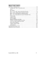
Страница 163: ...Copyright IBM Corp 1998 131 Safety Inspection Guide General Guidelines 132...

Страница 164: ...ould be used to identify possible safety conditions not covered by this Safety Inspection Guide If any unsafe conditions are present you must find out how serious the hazard is and if you can continue...

Страница 165: ...Type 2158 2163 Diskette Hard Drive 138 Assembly 3 Machine Type 2158 2163 CD DVD ROM Drive 139 Assembly 4 Machine Type 2158 2163 Monitor and Power Cord 141 Assembly 5 Machine Type 2158 2163 Keyboard a...

Страница 166: ...lgium Dutch BF Belgium French CA Canada CE Canada English CF Canada French CN China DK Denmark Danish FI Finland Finish FR France GE Germany HK Hong Kong IT Italy JP Japan LS LA Spanish ND Netherlands...

Страница 167: ...sm Index FRU Number Description Model 2158 Model 2163 1 1 20L2196 Front Panel X X 1 2 20L2197 Hard Drive Holder X X 1 2 36L9138 HDD Tray X X 1 3 20L2193 Top Cover X X 1 4 20L2194 Door Cover X X 1 NS 0...

Страница 168: ...and fan X 1 10 36L9122 AMD K6 2XT 350 MHz 100FSB w o heatsink and fan X 1 10 36L9123 AMD K6 2XT 380 MHz 95FSB w o heatsink and fan X 1 10 36L9124 AMD K6 2XT 400 MHz 100FSB w o heatsink and fan X 1 10...

Страница 169: ...atalog 137 1 14 36L9100 128MB module PC 100 X 1 15 00K8468 Power Supply 95W API Delta 854 1 071 V B H61 X X 1 16 01K4278 CMOS Backup Battery CR2032 X X Asm Index FRU Number Description Model 2158 Mode...

Страница 170: ...X X 2 3 36L9106 3 5 in 8GB Maxtor Quasar X X 2 3 36L9107 3 5 in 10GB Maxtor Quasar X X 2 3 36L9108 3 5 in 12GB Maxtor Quasar X X 2 3 36L9101 5 25 in 6GB Quantum Tsunami X X 2 3 36L9102 5 25 in 8GB Qu...

Страница 171: ...DE Cable w I 3Conn X X 3 4 20L2289 Audio Cable CD ROM X X 3 5 00N4265 56K GVC Non Voice Rockwell PCI NA SA Asia X X 3 5 00N4266 56K GVC Non Voice Rockwell PCI EMEA Australia New Zealand X X 3 5 00N426...

Страница 172: ...EMEA LA X X 3 6 36L9017 Modem Card Audio Cable X X 3 NS 36L9094 DVD ROM Hitachi X X 3 NS 00K8183 Phone Cord 7ft X X 3 NS 36L9126 Speaker Passive Zylux No Adapter Required X 3 NS 20L2168 Speaker Tier 1...

Страница 173: ...2158 Model 2163 4 NS 06J7900 CSA UL 10A 125V Cordset US CE CF LA AP X X 4 NS 01K4196 CE 10A 250V Volex Euro X X 4 NS 01K4198 UK 10A 250V Volex UK HK X X 4 NS 02K2648 T Mark 10A 125V w i adapter Japan...

Страница 174: ...X 5 1 12J5572 Rapid Access Denmark 105 keys X X 5 1 12J5581 Rapid Access Norwegian 105 keys X X 5 1 12J5580 Rapid Access Italy 105 keys X X 5 1 12J5588 Rapid Access Spain 105 keys X X 5 1 12J5564 Rapi...

Страница 175: ...2163 Zip Drive and Network Adapter Asm Index FRU Number Description Model 2158 Model 2163 6 1 28L1605 Iomega Zip Drive Z100ATAPI X X 6 2 08L2550 IBM Ethernet Adapter Lake Clark 1 6 X X 6 2 34L0409 3C...

Страница 176: ...RU Number Description Model 2158 Model 2163 7 Aptiva owners and servicers will need to call their local IBM HelpCenter to order the above software Application CD Pack Voice Type 3 0 Kit Lotus SmartSui...

Страница 177: ...7900 4 NS 141 06J7900 4 NS 141 08L2550 6 2 143 10L6656 3 NS 140 12J4546 5 NS 142 12J5558 5 1 142 12J5562 5 1 142 12J5564 5 1 142 12J5568 5 1 142 12J5569 5 1 142 12J5572 5 1 142 12J5573 5 1 142 12J5574...

Страница 178: ...9 36L9088 3 NS 140 36L9094 3 NS 140 36L9095 3 NS 140 36L9099 1 11 136 36L9100 1 14 137 36L9101 2 3 138 36L9102 2 3 138 36L9103 2 3 138 36L9104 2 3 138 36L9105 2 3 138 36L9106 2 3 138 36L9107 2 3 138 3...

Страница 179: ...y with drivers software updates product information and other file updates To access the BBS set your modem for eight data bits one stop bit and no parity bit The IBM PC Company Automated Fax Back Sys...

Страница 180: ...va information http www pc ibm com PC Company Home Page http www pc ibm com us aptiva Aptiva Home Page http www pc ibm com support Aptiva Product Specifications and Support http www pc ibm com us sear...

Страница 181: ...Copyright IBM Corp 1998 149 Appendix C Model Monitor Configurations and FRU Part Numbers For FRU replacement part numbers please see Parts Catalog on page 127...

Страница 182: ...150...

Страница 183: ...e 21 CD DVD ROM Drive BIOS Setup Utility 14 Check Procedure 54 CD DVD ROM Drive 4 CD ROM Drive 121 Connectors and Jumpers 123 Emergency exit 121 Emergency exitl 122 Front Panel 121 Front Panel 122 Cel...

Страница 184: ...Monitor Configurations and FRU Part Numbers 149 Modem Factory Installed Modem Card Connector Functions 116 Factory Installed Modem Card Layout 116 Modem 5 Monitor Check Procedure 61 Port Signals 127...

Страница 185: ...78 Bay 2 5 25 In Bay 79 Bay 3 3 5 In Bay 81 Bay 4 3 5 In Bay 81 Bay Panels 77 Cover 75 ESD Sensitive Parts 103 Identifying the Parts of the Sys tem 73 LED and Cable 100 Memory DIMM 85 Pentium II Proc...

Страница 186: ...Printed in U S A International Business Machines Corporation Old Orchard Road Armonk New York 10504 Part Number 37L2040 Pub Number S37L 2040 00 11 98...

Страница 187: ......

Отзывы: