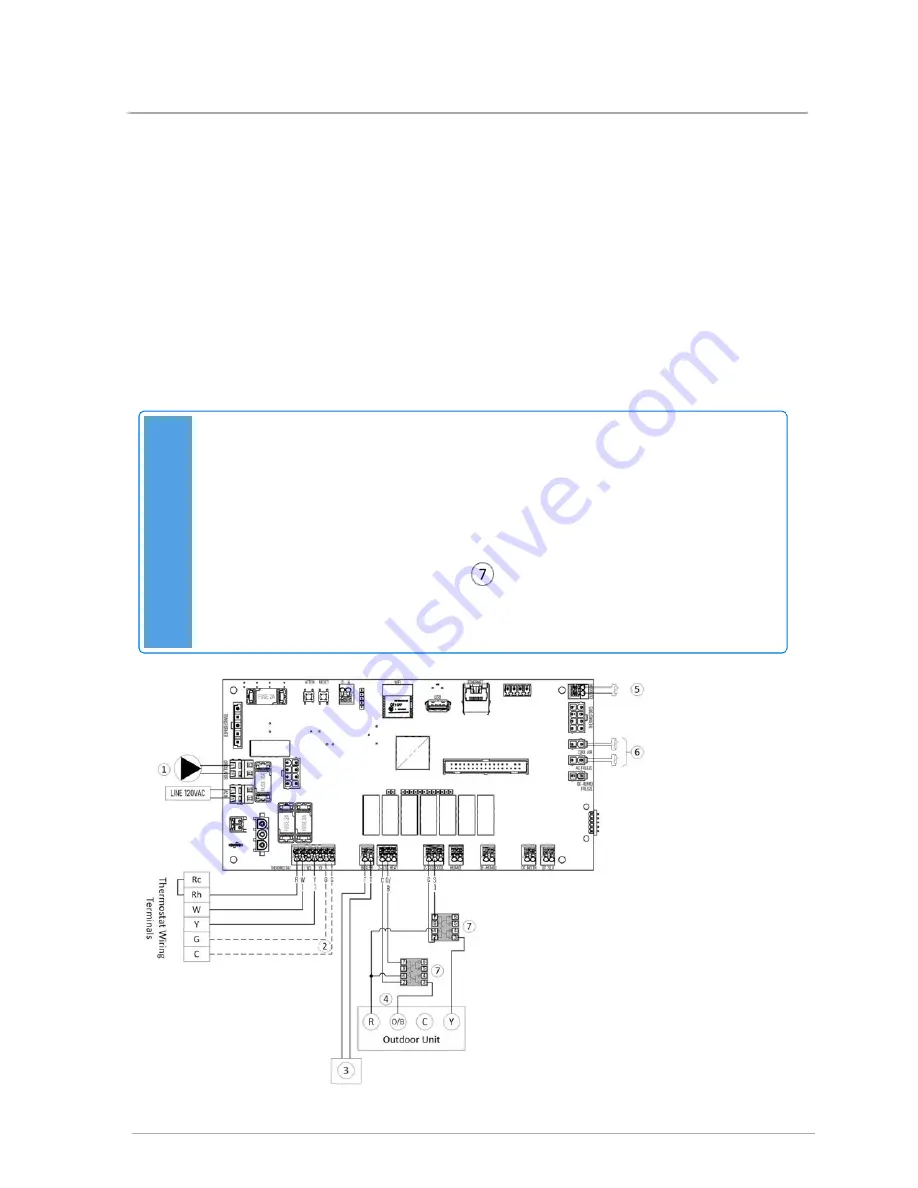
2.7.3 Connecting line voltage
Line voltage consists of a 120 VAC / 15 amp supply, external Pump – maximum 4 Amps 120 Volts,
thermostat connections – Standard TH Thermostat (communications thermostat protocol), external
pump control, boiler connection for a call for heat, and connection to an AC or HP appliance (air
handling appliance side only).
2.8 Worked examples
This section includes thirteen worked examples to help you set up the air handler for various
applications. Note that to configure the air handler, you need to download the
IBCconnect app
(see
Operating the air handler using the IBCconnect app on page 61
).
Note
If using an air conditioner or heat pump: consult the air conditioner or heat pump's wiring
instructions before connecting to the AHU. An air conditioner or heat pump producing its
own control voltage will require isolation relays.
If the air conditioner or heat pump's wiring diagram shows a thermostat connecting
directly to the air conditioner or heat pump's board (without an external transformer),
then isolation relays will be required. See
on
. If in doubt, power the air
conditioner or heat pump before connecting to it, and measure for voltage across control
contacts Y and C: a voltage greater than ~2 Volts AC or DC indicates that isolation relays
will be necessary.
35
2.7.3 Connecting line voltage
Содержание AHU 800
Страница 16: ...Figure 17 Left side return air opening Figure 18 Right side return air opening 14 Section Specifications...
Страница 44: ...5 Set Tankless Mode to Off 6 Tap SAVE 42 Section Installation...
Страница 48: ...4 Set Boiler Heating to Boiler Backup 5 Set Tankless Mode to On 6 Tap SAVE 46 Section Installation...
Страница 53: ...5 Set Tankless Mode to On 6 Tap SAVE 51...
Страница 55: ...5 Set Tankless Mode to On 6 Tap SAVE 53...
Страница 57: ...7 Set FA Damper Open T F to lowest Fresh Air temperature 8 Tap SAVE 55...
Страница 58: ...This page is intentionally left blank...
Страница 60: ...This page is intentionally left blank...
Страница 74: ...This page is intentionally left blank...
Страница 88: ...7 Air handling appliance parts diagram 86 Section Air handling appliance parts diagram...
Страница 90: ...88 Section Air handling appliance parts diagram...
Страница 91: ...8 Appendice Wiring diagram Figure 52 AHU Air handler internal wiring diagram 89 8 Appendice Wiring diagram...


