AST1257-940
Page
12
Water Line Connection
A bypass valve system must be installed to provide
for occasions when the water conditioner must is by-
passed for hard water or for servicing. The most
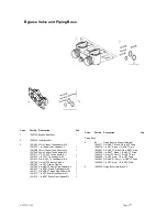
common bypass systems are the Autotrol Series 156
Bypass Valve, Figure 3, and plumbed-in globe
valves, Figure 4. Though both are similar in function,
the Autotrol Bypass offers simplicity and ease of
operation.
Drain Line Connection
The drain line discharges water and brine during the
regeneration cycles. Typically, the line drains into a
floor drain or laundry tube. Plumb the drain line
according to local codes, leaving a one or two inch air
gap between the end of the drain line and the open-
ing, Figure 5.
Caution
Never connect the drain line into a drain,
sewer line or trap. Always allow an air gap
between the drain line and the wastewater
to prevent the possibility of sewage being
back-siphoned into the conditioner.
The ideal location for the unit is above and not more
than 20ft (6.1m) from the drain. For such installations,
using the appropriate adaptor fitting (not supplied),
connect 1/2 in (1.3cm) plastic tubing to the drain line
connection located at the rear of the control.
If the unit is located more than 20ft (6.1m) from the
drain, use 3/4in (1.9cm) tubing for runs up to 40ft
(12.2m). You may elevate the line up to 6ft (1.8m)
providing the run does not exceed 15ft (4.6m) and the
water pressure at the conditioner is not less than
40psi (280kPa). You may elevate an additional 2ft
(61cm) for each additional 10psi (70kPa) of water
pressure. When the drain line is elevated and empties
into a drain which is below the level of the control
valve, form a 7 inch (17cm) loop at the drain end of
the line so that the bottom of the loop is level with the
drain line connection. This provides an adequate
siphon trap. If the drain empties into an overhead
sewer line, a sink-type trap must be used.
Note:
The above instructions reflect standard
commercial practices. Local codes may require
different installation procedures.
Brine Line Connection
Install the brine tube and connect to the fitting
connection located on the air check on the tank
adaptor module, see Figure 2.
Note:
Make sure that all fittings and connections are
tight so that premature checking does not take place.
Premature checking occurs when the ball in the air
check falls to the bottom before all brine is drawn out
of the brine tank. Refer to the
Troubleshooting
section in this manual for additional information.
Brine Tank Overflow Line Connection
In the event of a malfunction, the tank overflow
connection directs overflow to the drain instead of
spilling on the floor where it could cause water
damage. Complete the following steps to connect the
overflow fitting to the brine tank:
1. Locate the fitting hole on the side of the brine
tank.
Not In Bypass
In Bypass
Not In Bypass
In Bypass
Figure 3 - Autotrol Series 156 Bypass Valve
Figure 4 - Typical Globe Valve Bypass
System
Figure 5 - Air Gap Installation
Содержание AST1257-940
Страница 20: ...AST1257 940 Page 20 Control Valving Identification Valve Disc Operation...
Страница 21: ...AST1257 940 Page 21 Flow Diagrams...
Страница 22: ...AST1257 940 Page 22...
Страница 24: ...AST1257 940 Page 24...
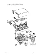
Страница 25: ...AST1257 940 Page 25 Valve Body and Tank Adaptor Module...
Страница 29: ...AST1257 940 Page 29...


