background image


17 


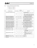
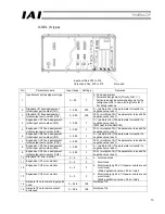
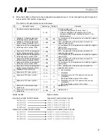
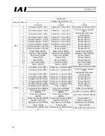
No. Parameter 

name Input 

range 

Settings

Remarks 

Input/output port assignment 
type 

0 ~ 20 

0: Fixed assignment 
1: Automatic assignment (Priority: Slot 1 ~) 
*  Ports are assigned automatically only for 

the contiguous slots in use, starting from 
slot 1 = For safety reasons. 

Standard I/O fixed assignment: 
Initial input port number (I/O1) 

-1 ~ 599 

032 

0 + (multiple of 8) (The parameter is invalid if 
a negative value is set.)   

Standard I/O fixed assignment: 
Initial output port number (I/O1) 

-1 ~ 599 

316 

300 + (multiple of 8) (The parameter is 
invalid if a negative value is set.)   

Expansion I/O1 fixed 
assignment: Initial input port 
number (I/O2) 

-1 ~ 599 

000 

0 + (multiple of 8) (The parameter is invalid if 
a negative value is set.)   

(Slot next to standard I/O)


Expansion I/O1 fixed 
assignment: Initial output port 
number (I/O2) 

-1 ~ 599 

300 

300 + (multiple of 8) (The parameter is 
invalid if a negative value is set.)   

Expansion I/O2 fixed 
assignment: Initial input port 
number (I/O3) 

-1 ~ 599 

-1 

0 + (multiple of 8) (The parameter is invalid if 
a negative value is set.)   

Expansion I/O2 fixed 
assignment: Initial output port 
number (I/O3) 

-1 ~ 599 

-1 

300 + (multiple of 8) (The parameter is 
invalid if a negative value is set.)   

Expansion I/O3 fixed 
assignment: Initial input port 
number (I/O4) 

-1 ~ 599 

-1 

0 + (multiple of 8) (The parameter is invalid if 
a negative value is set.)   

Expansion I/O3 fixed 
assignment: Initial output port 
number (I/O4) 

-1 ~ 599 

-1 

300 + (multiple of 8) (The parameter is 
invalid if a negative value is set.)   

10  Standard I/O error monitor 

0 ~ 5 

0:  Not monitored 

11  Expansion I/O1 error monitor 

0 ~ 5 

1:  Monitored 

12 

Expansion I/O2 error monitor 

0 ~ 5 

2:  Monitored (only 24-V I/O power errors 

are not monitored)   

13 

Expansion I/O3 error monitor 

0 ~ 5 

3:  Monitored (only 24-V I/O power errors 

are not monitored). 


(Main application version 0.55 or later) 

14 

Network I/F card remote input 
ports used 

0 ~ 256 

256 

Multiple of 16 

15 

Network I/F card remote output 
ports used 

0 ~ 256 

256 

Multiple of 16 


Содержание X-SEL Series

Страница 1: ...ter GmbH Ober der R th 4 D 65824 Schwalbach Taunus Phone 06196 8895 0 Fax 06196 8895 24 E Mail info iai gmbh de Internet http www eu iai gmbh de Document BA Profibus DP EU E Profibus Card Version 3 E...

Страница 2: ...5 Monitor LED indications 8 3 3 Setting X SEL I O Parameters Assigning I O Ports 9 3 3 1 Board Installation Positions Slots and I O Parameters 9 1 J type compact type 9 2 K type 10 3 3 2 Factory set...

Страница 3: ...3 Bus termination settings 27 4 Node address settings 27 5 Monitor LED indications 28 6 Input output I O signal assignments 29 7 Correspondence of RCS C E Con and Scon I O port numbers and PLC addres...

Страница 4: ...d as slave stations remote I O terminals capable of communicating I O data For details on ProfiBus DP refer to the operation manual for the programmable controller hereinafter referred to as PLC in wh...

Страница 5: ...igurations Baud rate kbps 1 Maximum distance over the entire network Baud rate Cable type 100 m 12 000 6 000 3 000 kbps 200 m 1 500 kbps 400 m 500 kbps 1000 m 187 5 kbps Transmission distance 1200 m 9...

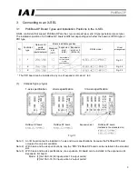
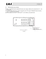
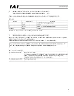
Страница 6: ...the ProfiBus DP board occupies the only slot available Note 2 With 3 axis and 4 axis specifications only the PR0 ProfiBus DP board can be installed in the standard slot Note 3 With 3 axis and 4 axis s...

Страница 7: ...O1 slot at the far left z The PR1 ProfiBus DP board occupies two expansion slots If this type of ProfiBus DP board is selected only one expansion slot can be used z Either an expansion I O board 1 or...

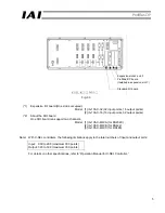
Страница 8: ...05 X MW A for RS232C 2 IA 105 X MW B for RS422 3 IA 105 X MW C for RS485 Note With X SEL controllers the following limitations apply to the total numbers of input and output ports Input 000 to 299 max...

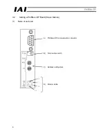
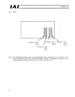
Страница 9: ...6 3 2 Setting a ProfiBus DP Board Slave Station 1 Name of each part A ProfiBus DP communication connector B Termination switch C Address setting dials D Monitor LEDs...

Страница 10: ...a ProfiBus DP network the devices at both ends require termination to prevent reflected waves from entering the bus line again This ProfiBus DP module provides a termination switch that makes this ter...

Страница 11: ...Accordingly numbers 1 to 99 are available for slave stations Note 2 The node address of each slave station set above cannot be changed while the slave is communicating with the master 5 Monitor LED i...

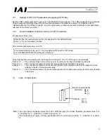
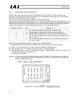
Страница 12: ...is normally 2 Take note that the above setting can be changed in a range of 0 to 3 at the user s responsibility If set to 0 The controller does not monitor any error occurring in the board installed i...

Страница 13: ...o 1 and No 11 to 0 when a ProfiBus DP board is set in the slots denoted by A above If a ProfiBus DP board is set in the slots denoted by B Nos 8 and 9 are set to 1 while No 13 is set to 0 Parameter No...

Страница 14: ...is set 6 Expansion I O2 fixed assignment Initial input port number I O3 1 599 1 1 000 0 multiple of 8 The parameter is invalid if a negative value is set 7 Expansion I O2 fixed assignment Initial out...

Страница 15: ...port 0 Default setting 3 300 Standard DOs are assigned from output port 300 Default setting 14 n The number of ProfiBus DP input points is specified as a multiple of 16 16 n 256 15 m The number of Pro...

Страница 16: ...nitial input port number I O3 1 599 1 0 multiple of 8 The parameter is invalid if a negative value is set 7 Expansion I O2 fixed assignment Initial output port number I O3 1 599 1 300 multiple of 8 Th...

Страница 17: ...nstalled in expansion slot I O1 when the maximum numbers of inputs and outputs of the ProfiBus DP slave station are 256 and 256 respectively entering 256 in I O parameter Nos 14 and 15 will automatica...

Страница 18: ...lue is set 6 Expansion I O2 fixed assignment Initial input port number I O3 1 599 1 0 multiple of 8 The parameter is invalid if a negative value is set 7 Expansion I O2 fixed assignment Initial output...

Страница 19: ...lot is assigned for the subsequent numbers 1 Enter 1 in I O parameter No 1 to specify fixed assignment 2 Set I O parameter 4 Expansion I O 1 fixed assignment Initial input port number to 0 3 Set I O p...

Страница 20: ...lue is set 6 Expansion I O2 fixed assignment Initial input port number I O3 1 599 1 0 multiple of 8 The parameter is invalid if a negative value is set 7 Expansion I O2 fixed assignment Initial output...

Страница 21: ...pose input 305 General purpose output 006 General purpose input 306 General purpose output 007 Program specification PRG No 1 307 General purpose output 008 Program specification PRG No 2 308 General...

Страница 22: ...re assigned in units of 16 bits 16 I O points i e they are assigned in units of words The example below illustrates the relationship of X SEL I O port numbers and PLC I O addresses according to the X...

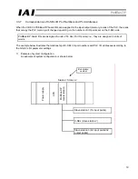
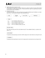
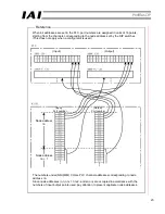
Страница 23: ...the PLC The bit address description rules are specified below Prefix Bus station number This number indicates which of the units installed in the PLC is the ProfiBus DP master unit Refer to the figure...

Страница 24: ...et 6 Expansion I O2 fixed assignment Initial input port number I O3 1 599 1 0 multiple of 8 The parameter is invalid if a negative value is set 7 Expansion I O2 fixed assignment Initial output port nu...

Страница 25: ...er station Eight input words Eight output words Slave station 1 16 input points Slave station 2 64 output points Slave station 3 32 input points No applicable slave station Slave station 2 64 input po...

Страница 26: ...This does not apply when a configurator is used Input Output Input Output Port number Port number Node address nn Node address nn 1 The numbers under NN MM CH are PLC channel addresses corresponding t...

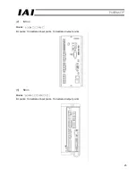
Страница 27: ...on 4 1 Models External views front views of the RCS E Con and Scon controllers that support ProfiBus DP are shown below 1 RCS C Models I O points Eight dedicated input points 10 dedicated output point...

Страница 28: ...25 2 E Con Models I O points 10 dedicated input points 12 dedicated output points 3 SCon Models I O points 16 dedicated input points 16 dedicated output points...

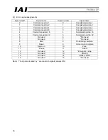
Страница 29: ...A This is a 9 pin female D sub connector recommended by the ProfiBus DP standard EN 50170 Connector Pin No Description Contents 3 B Line RxD TxD Positive signal line 5 GND Shield 8 A Line RxD x TxD Ne...

Страница 30: ...tc may result Termination switch OFF Termination disabled 4 Node address settings Set by the address setting dials 1 D The address of a slave station is set using the upper rotary switch ADRS H and lo...

Страница 31: ...e is operating normally The module is connected to the fieldbus and is therefore in online state ERR Red On Offline or communication error The module is not connected to the fieldbus and is therefore...

Страница 32: ...ation Manual for E Con Controller and Operation Manual for Scon Controller 1 RCS C signal assignments Input number Signal name Output number Signal name 0 Command position 1 0 Completed position 1 1 C...

Страница 33: ...on 8 3 Completed position 8 4 Command position 16 4 Completed position 16 5 Command position 32 5 Completed position 32 6 Not used 6 Not used 7 Not used 7 Not used 8 Start 8 Positioning complete 9 Res...

Страница 34: ...write CSTR PWRT Start CSTR 14 Alarm reset RES Alarm reset RES Alarm reset RES Input 15 Servo on SON Servo on SON Servo on SON 0 Completed position PM1 Completed position PM1 Completed position PM1 1...

Страница 35: ...set RES Alarm reset RES Input 15 Servo on SON Servo on SON Servo on SON 0 Completed position PM1 Position No 0 complete PE0 Rear end move command LS0 1 Completed position PM2 Position No 1 complete PE...

Страница 36: ...re connected as slave stations to the master station 1 Example of system configuration An example of system configuration is shown below 2 Address assignment in the master station When setting the con...

Страница 37: ...the installation position of the ProfiBus DP board in the PLC Prefix Word number Bit address Bus station number Input bit address address per bit Input word address address per word Output bit address...

Страница 38: ...is not used This area is not used This area is not used This area is not used This area is not used This area is not used This area is not used Slave station 1 RCS 8 input points Slave station 2 E Con...

Страница 39: ...sequentially assigned to the channels corresponding to the node address set by the DIP switches Input Output Node address nn The numbers under NN MM CH are PLC channel addresses corresponding to node...

Страница 40: ...or errors 5 3 GDS Files For the ProfiBus DP configurator use the configurator recommended for the master unit If GDS files are needed to use the recommended configurator download the applicable files...

Страница 41: ...net http www eu IAI GmbH de IAI America Inc 2690 W 237th Street Torrance CA 90505 USA Tel 1 310 891 6015 Fax 1 310 891 0815 IAI CORPORATION 645 1 Shimizu Hirose Shizuoka 424 0102 Japan Tel 81 543 64 5...

Отзывы: