


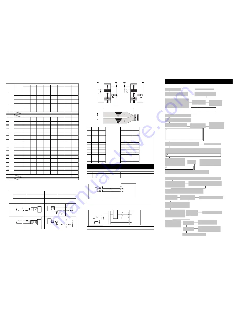
Signal Assignment for Each Mode
The signal assignment of I/O flat cable by the PIO pattern is as shown below. Follow the following table to connect the external
equipment (such as PLC).
Selection in Parameter No. 25 (PIO Pattern)
0 1 2 3 4 5 6
Category PIO
Functions
Positioning
mode
Teaching
mode
256-point
mode
512-point
mode
Electro-
magnetic
valve mode
1
Electro-
magnetic
valve mode
2
Pulse train
control mode
(For
Incremental )
Pulse train
control mode
(For
Battery-less
Absolute
Number of
Positioning Points
64 points
64 points
256 points
512 points
7 points 3
points
–
–
Home Return
Signal
{
{
{
{
{
×
{
{
Jog Signal
×
{
×
×
×
×
×
×
Teaching Signal
(Current Position
Writing)
×
{
×
×
×
×
×
×
Input
Brake Release
{
×
{
{
{
{
{
{
Signal during
Operation
{
{
×
×
×
×
×
×
Zone Signal
{
Δ
(Note1)
Δ
(Note1)
×
{
{
{
{
Pin
No.
Output
Position Zone
Signal
{
{
{
×
{
{
×
×
1A 24V
P24
2A 24V
P24
3A –
–
PP
PP
4A –
–
/PP
/PP
5A IN0
PC1
PC1
PC1
PC1
ST0
ST0
SON
SON
6A IN1
PC2
PC2
PC2
PC2
ST1
ST1
(JOG
+
)
RES RES
7A IN2
PC4
PC4
PC4
PC4
ST2
ST2
(Note2)
HOME HOME
8A IN3
PC8
PC8
PC8
PC8
ST3
–
TL
TL
9A IN4
PC16
PC16
PC16
PC16
ST4
–
CSTP
CSTP
10A IN5
PC32
PC32
PC32
PC32
ST5
–
DCLR
DCLR
11A IN6
–
MODE
PC64
PC64
ST6
–
BKRL
BKRL
12A IN7
–
JISL
PC128
P128
–
–
RMOD
RMOD
13A IN8
–
JOG
+
–
PC256
– – –
RSTR
14A IN9
BKRL
JOG
−
BKRL BKRL BKRL BKRL –
–
15A IN10
RMOD
RMOD
RMOD
RMOD
RMOD
RMOD
–
–
16A IN11
HOME
HOME
HOME
HOME
HOME
–
–
–
17A IN12
*STP
*STP
*STP
*STP
*STP
–
–
–
18A IN13
CSTR
CSTR/PW
RT
CSTR
CSTR
– – – –
19A IN14
RES
RES
RES
RES
RES
RES
–
–
20A
Input
IN15 SON
SON
SON
SON
SON
SON – –
1B OUT0
PM1
(ALM1)
PM1
(ALM1)
PM1
(ALM1)
PM1
(ALM1)
PE0 LS0 PWR PWR
2B OUT1
PM2
(ALM2)
PM2
(ALM2)
PM2
(ALM2)
PM2
(ALM2)
PE1
LS1
(TRQS)
SV SV
3B OUT2
PM4
(ALM4)
PM4
(ALM4)
PM4
(ALM4)
PM4
(ALM4)
PE2
LS2
(Note2)
INP INP
4B OUT3
PM8
(ALM8)
PM8
(ALM8)
PM8
(ALM8)
PM8
(ALM8)
PE3 – HEND
HEND
5B OUT4
PM16
PM16
PM16
PM16
PE4
–
TLR
TLR
6B OUT5
PM32
PM32
PM32
PM32
PE5
–
*ALM
*ALM
7B OUT6
MOVE
MOVE
PM64
PM64
PE6
–
*EMGS
*EMGS
8B OUT7
ZONE1
MODES
PM128
PM128
ZONE1
ZONE1
RMDS
RMDS
9B OUT8
PZONE/
ZONE2
PZONE/
ZONE1
PZONE/
ZONE1
PM256
PZONE/
ZONE2
PZONE/
ZONE2
ALM1 ALM1
10B OUT9
RMDS
RMDS
RMDS
RMDS
RMDS
RMDS
ALM2
ALM2
11B OUT10
HEND
HEND
HEND
HEND
HEND
HEND
ALM4
ALM4
12B OUT11
PEND
PEND/
WEND
PEND PEND PEND – ALM8 ALM8
13B OUT12
SV
SV
SV
SV
SV
SV
*ALML
*ALML
14B OUT13
*EMGS
*EMGS
*EMGS
*EMGS
*EMGS
*EMGS
–
REND
15B
OUT14 *ALM *ALM *ALM *ALM *ALM *ALM ZONE1 ZONE1
16B
Output
OUT15
(Note3)
LOAD/TRQS
*ALML
/*BALM
*ALML
/*BALM
LOAD/TRQS
*ALML
/*BALM
LOAD/TRQS
*ALML
/*BALM
LOAD/TRQS
*ALML
/*BALM
*BALM/
*ALML
ZONE2 ZONE2
17B –
–
NP
NP
18B –
–
/NP
/NP
19B 0V
N
20B 0V
N
(Note) “*” in codes above shows the signal of the active low.
PM1 to PM8 indicate the alarm binary code output signal when an alarm is generated. [Refer to the Instruction Manual
for the details]
(Note 1) The setting can be changed over to PZONE if set in the parameter setting.
(Note 2) It is invalid before home-return operation.
(Note 3) *BALM is dedicated for ACON.
PIO Input and Output Interface
Input section
Output section
Input voltage
24V DC
±
10%
Load voltage
24V DC
Input current
5mA 1 circuit
Peak load electric
current
50mA/1 point
S
pecifi
ca
tion
ON/OFF voltage
ON voltage MIN. 18V DC
OFF voltage MAX. 6V DC
Leak Current
MAX. 2mA/1 point (PCON)
MAX. 1mA/1 point
(ACON, DCON)
NP
N
680
5.6K
P24
External
Power Supply
24V DC
Input
Terminal
Internal
Power
Source
Controller
15
P24
N
Load
External
Power Supply
24V DC
Output
Terminal
Internal
Power
Source
Controller
PNP
680
5.6K
N
External
Power Supply
24V DC
Input
Terminal
Internal
Power
Source
Controller
15
P24
N
Load
External
Power Supply
24V DC
Output
Terminal
Internal
Power
Source
Controller
NPN Specification
PNP Specification
I/O Cable
Model
:
CB-PAC-PIO
□□□
(Enter the cable length (L) in
□□□
Example. 020
=
2m)
No. Signal Name Cable Color
Wiring
No.
Signal Name Cable Color
Wiring
1A 24V BR-1
1B OUT0 BR-3
2A 24V RD-1
2B OUT1 RD-3
3A PP OR-1
3B
OUT2 OR-3
4A /PP YW-1
4B
OUT3 YW-3
5A IN0 GN-1
5B
OUT4 GN-3
6A IN1 BL-1
6B
OUT5 BL-3
7A IN2 PL-1
7B
OUT6 PL-3
8A IN3 GY-1
8B
OUT7 GY-3
9A IN4 WT-1
9B
OUT8 WT-3
10A IN5 BK-1
10B
OUT9 BK-3
11A IN6 BR-2
11B
OUT10 BR-4
12A IN7 RD-2
12B
OUT11 RD-4
13A IN8 OR-2
13B
OUT12 OR-4
14A IN9 YW-2
14B
OUT13 YW-4
15A IN10 GN-2
15B
OUT14 GN-4
16A IN11 BL-2
16B
OUT15 BL-4
17A IN12 PL-2
17B
NP
PL-4
18A IN13 GY-2
18B
/NP
GY-4
19A IN14 WT-2
19B
0V
WT-4
20A IN15 BK-2
Flat Cable
○
A
(Insulation-Displacement
Connectors)
AWG28
20B
0V BK-4
Flat Cable
○
B
(Insulation-Displacement
Connectors)
AWG28
Operation in Pulse Train Control Mode
(function for PLN and PLP Types only)
Pulse Train Input and Output Interface
Category Abbreviated Code
Signal Name
Contents of Functions
PP, /PP
Input
NP, /NP
Command Pulse Input
Inputs the command pulse train.
Input pulse frequency differs depending on the type.
[Refer to Basic Specifications]
●
When Host Unit is Differential System
(Although the example shows PCON, it is the same for ACON and DCON.)
Note1 : Use the same power source (0V) for the host open collector output, AK-04.
●
When Host Unit is Open Collector System [AK-04 (option) is required]
(Although the example shows PCON, it is the same for ACON and DCON.)
Note1 : 1) Use the same power source (0V) for the host open collector output, AK-04.
2) Have the cables as short as possible between the host unit and AK-04.
Starting Procedures
When using this product for the first time, make sure to avoid mistakes and incorrect wiring by referring to
the procedure below. “PC” stated in this section means “PC software”.
Pin No.
Pin No.
Load
Load
Flat Cable (20-core)
×
2
BK-4
BR-3
BK-2
BR-1
No treatment
conducted
No treatment
conducted
20A
20B
1A
1B
Half Pitch MIL Socket
HIF6-40D-1.27R (Hirose Electric)
A
B
L
0V
24V
DC
0V
0V
1
2
3
4
1
2
3
4
PCON
PIO Connector
3A
4A
17B
18B
19B
20B
Host Unit
Positioning Unit
Pulse
Command
0V
0V
PP
/PP
NP
/NP
/PP
PP
NP
/NP
NP
PP
0V
24V
Pulse Converter
AK-04
(to be purchased separately)
24V
PCON
PIO Connector
3A
4A
17B
18B
Host Unit
Positioning Unit
Pulse Command
(Line Driver:
26C31 or equiv.)
PP
/PP
NP
/NP
→
No →
Contact us or our distributor.
↓ Yes
No →
→
↓ Yes
← Yes
→
No →
Check Item
Is the Controller Status Display
LED turned ON in green [SV]?
Check the emergency stop circuit.
→
No →
↓ Yes
↓ Yes
↓
Check if there is any problem with the
installation of the actuator and the condition
of the actuator use exceeds the ranges of the
rated values.
Adjust the servo if necessary.
If an alarm is generated,
connect the PC or teaching
pendant and check the
content of the alarm to have
the right treatment.
Check Item
Any vibration or
abnormal noise?
No →
↓ Yes
Point Check Item
• Is frame ground (FG) connected?
• Has the noise countermeasure been taken?
Check Item
Is the Controller Status
Display LED turned OFF?
Connect the teaching tool
such as PC to confirm the
content of alarm and have
an appropriate treatment.
Have the settings and checks suitable for the used
mode selected from “Positioner Mode” and “Pulse
Train Control Mode” below.
[In the case of Positioner Mode]
Check of Packed Items
Are there all the delivered items?
Installation and Wiring
Perform the installation of and wiring for the
actuator and controller.
Power Supply and Alarm Check
Connect a teaching tool such as PC, turn the
operation mode setting switch to “MANU” side and
turn the power ON for unit.
Select [Teaching Mode 1 Safety Speed Activated /
PIO Operation Invalid] in the teaching tool such as
PC.
PIO Pattern Settings
Set the used PIO pattern to Parameter No.25.
Safety Speed Setting
Set the Parameter No.35 if necessary.
The safety speed is set to 100mm/s at the delivery.
Servo ON
Turn the servo ON with the operation on the
teaching tool such as PC.
Caution
Please perform this process with the actuator away from the mechanical end or
interfering subjects as much as possible.
Put the actuator away if it interferes with surroundings. It may generate an alarm
if the actuator hit the mechanical end or interfering subjects when the servo is
turned ON.
The slider may get slightly dropped by self-weight if servo ON and OFF is
repeatedly performed at the same position. Be careful not to pinch the hand or
damage the work.
Safety Circuit Check
Does the emergency stop circuit (drive cutoff circuit) work properly and
turn the servo OFF?
Target Position Setting
Set the target position in “Position” Box in each position table.
Perform a home-return operation first when Direct Teaching is to be performed. When moving the actuator manually, set
the Brake Release Switch to “BK RLS” side for the brake equipped type. Put the switch back after the setting is complete.
Test Run Adjustment 1
Check the operation without mounting a
work and set the safety speed invalid on
the teaching tool such as PC, and then
check the operation with a work mounted.
Caution To ensure safety, it is recommended that safety
speed be enabled during initial movements.
Test Run Adjustment 2
1) Set the operation mode setting switch to “AUTO”.
2) Output the operation command from PLC to the controller and check the system operation.
Warning Be careful not to pinch fingers or damage the work with the dropped actuator when releasing the brake
in vertical orientation.
→
Check Item
Is the minimum unit of operation set to the value bigger than the
minimum resolution of the encoder?
Is the fraction of the electronic gear ratio reduced to its lowest terms?
← Yes
→
Check Item
Is the Controller Status Display
LED turned ON in green [SV]?
No → Confirm the content of alarm on the teaching
tool such as PC to have an appropriate treatment.
← Yes
↓ Yes
→
No →
No → Check the electronic gear ratio setting.
Confirm the command pulse train input
mode setting.
Confirm that there is no problem in the
actuator installation, the actuator operation
condition demands a voltage more than rated
voltage, and appropriate pulse trains are input.
Check if there is any problem in the way
of actuator mount.
Check Item
Is there any risk of
interfering with peripheral
equipment?
No →
↓ Yes
Can the positioning
operation be performed
normally?
↓ Yes
↓ Yes
Is it in condition without
any vibration and
abnormal noise?
Test Run Adjustment 3
Check the system operation conducted by PLC.
PIO Pattern Settings
Set the used 6 “Pulse train control mode” or 7 “Pulse train control mode for Battery-less Absolute” to Parameter No.25.
Set the Electronic Gear
[Refer to Instruction Manual]
Set the electronic gear ratio based on the
amount of actuator operation per pulse in
Parameters No.65 and 66.
Pulse Train Input Output Mode Setting [Refer to Instruction Manual]
Set the command pulse train input status for the parameter No.63 and No.64.
Put Operation Mode Setting Switch to “AUTO” side when the setting is complete.
Servo ON
Input servo ON signal
from PLC.
Safety Circuit Check
Check that the emergency stop circuit (or motor
drive-power cutoff circuit) operates normally to turn
OFF the servo.
Test Run Adjustment 1
[Operation Mode MANU]
Check with a teaching tool such as the
PC software with no work being loaded,
and check the operation range with JOG
operation with the work being loaded.
Test Run Adjustment 2
[Operation Mode AUTO]
Output the pulse train from PLC
to the controller and check the
system operation.
[In the case of Pulse Train Control Mode (for PLN and PLP types only)]


