16
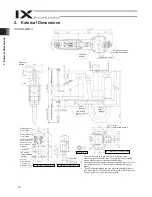
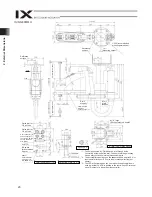
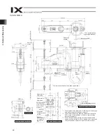
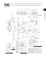
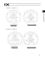
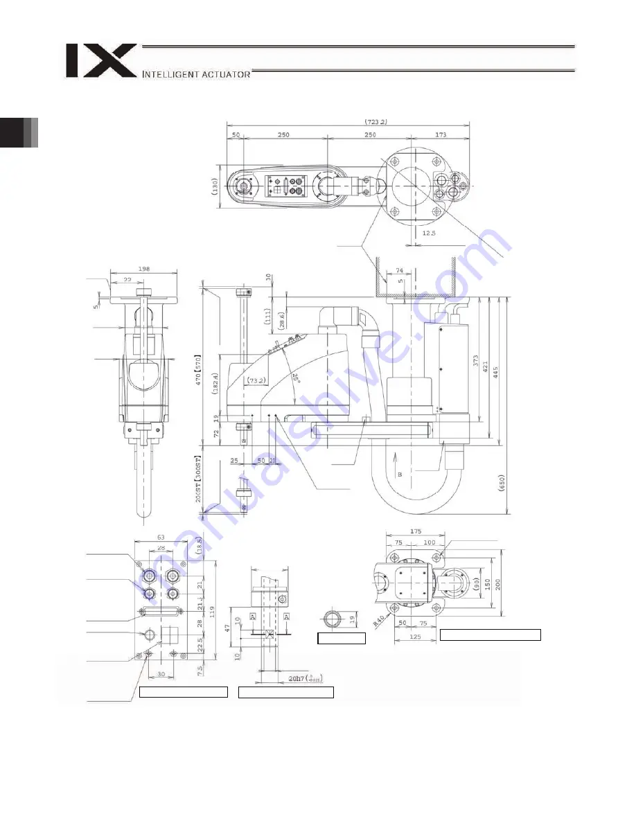
2. External Dimensions
Reference
surface
(Mounting center)
235 (recommended
mounting dimension)
Reference
surface
5.5 (Mecha
nical
en
d)
5 (Mechani
cal e
nd)
Arm 2
stopper
3-M4, depth 8
Same on opposite
side (*1)
Arm 1,
arm2
stopper
Quick joint for
6 air tube
Quick joint for
4 air tube
User connector (D-
sub connector for
user wiring, 25-pin,
socket, fastener
size M2.6)
ALM (*3)
BK switch
(brake release
switch)
Spacer
Outer diameter
7, height 10,
M4, depth 5 (*2)
Detail view of panel (1/2)
Detail vew of arm tip (1/2)
14 hollow
Section A-A
B: Detail view of base mount
4-
11, large
24 counterbored, depth 5
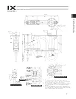
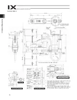
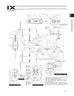
*1: The holes denoted by “3-M4, depth 8” are through holes
connecting both sides of the arm. Take note that long mounting
screws may contact the internal mechanism parts.
*2: The external force acting upon the spacer shall be kept to 30 N or
less in axial direction or 2 N
m or less in rotating direction (per
spacer).
*3: The LED will actuate when the user wires the applicable lines in
such a way that 24 VDC is applied to the user-wired LED terminal
upon I/O output of a signal from the controller.
112
146
44
black
red yellow
white
2. External
Dimensions
IX-HNN-50
H
Содержание IX Series
Страница 2: ......
Страница 4: ......
Страница 56: ...50 9 How to Install ...
Страница 58: ...52 9 How to Install Center of recommended installation part ...
Страница 95: ...89 13 Maintenance and Inspection 6 Click the Servo OFF button Servo OFF 7 Press the emergency stop switch ...
Страница 104: ......
Страница 105: ......


