background image

9

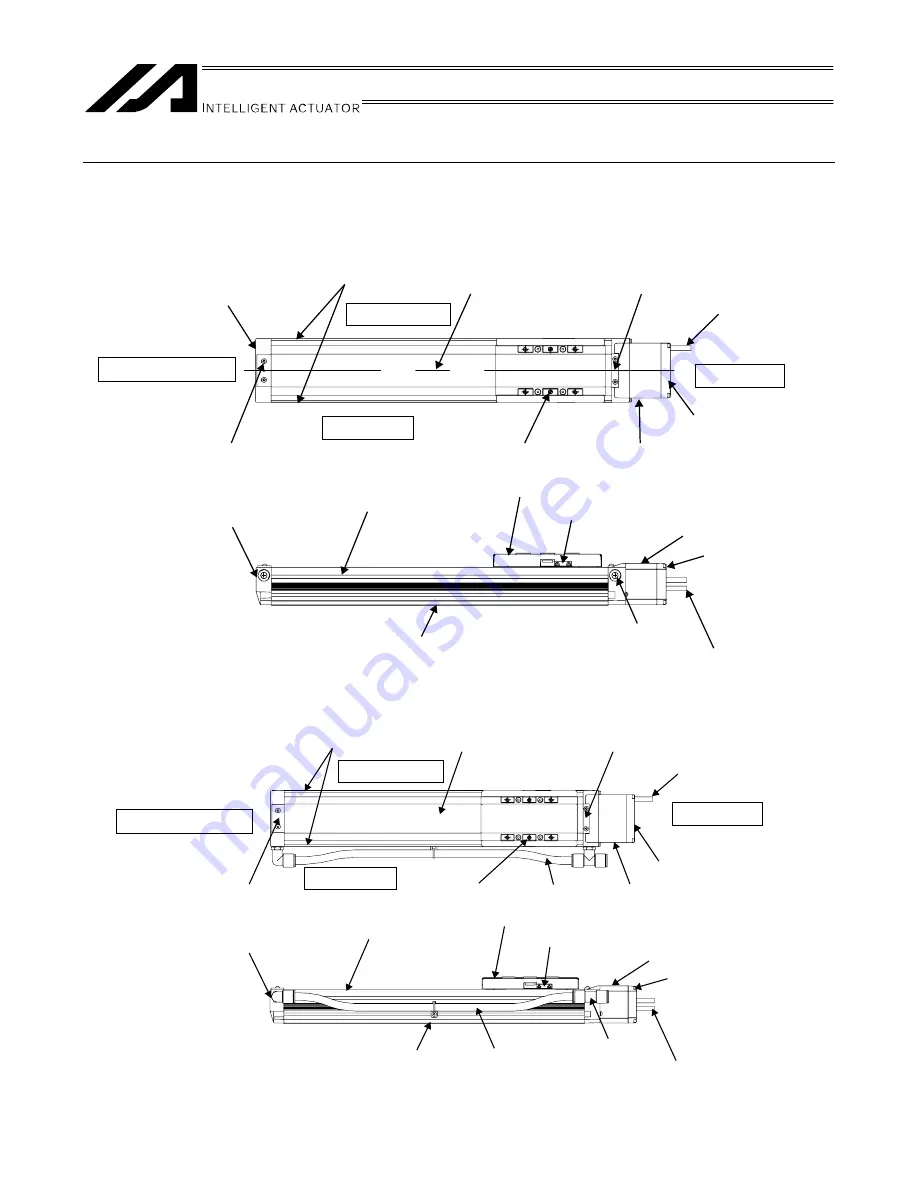
Names of the Parts 

In this operating manual, the left and right sides are indicated by looking at the actuator from the motor end, with 

the actuator placed horizontally, as shown in the figure below. 

1.  ISDB/ISPDB 

2.  ISDBCR/ISPDBCR 

Right side (R)

Left side (L)

Motor cover 

Slider

Front cover 

Base 

Actuator cable 

Front side 

Motor side

Coupling cover 

Rear cover

Coupling cover 

Left side (L)

Front side 

Motor side

Slider

Front cover 

Base 

Actuator cable 

Motor cover 

Rear cover

Stainless sheet 

Sheet cover plate 

Side cover

Slider cover

Plug screw 

Air tube 

Air piping joint

Side cover 

Front cover 

Motor cover 

Rear cover 

Actuator cable 

Side cover

Sheet cover plate 

Air tube

Stainless sheet 

Actuator cable 

Rear cover 

Motor cover 

Slider cover

Grease nipple 

Grease nipple 

Side cover

Right side (R)

Содержание IS Cast SSPDACR

Страница 1: ...IAI America Inc ISDB Series Actuator Operating Manual Tenth Edition ISDB ISDBCR ISPDB ISPDBCR IS Cast SSPDACR ...

Страница 2: ......

Страница 3: ...the Operating Manual keep it in a convenient place so that whoever is handling this product can reference it quickly when necessary Important x This Operating Manual is original x The product cannot be operated in any way unless expressly specified in this Operating Manual IAI shall assume no responsibility for the outcome of any operation not specified herein x Information contained in this Opera...

Страница 4: ...CE Marking If a compliance with the CE Marking is required please follow Overseas Standards Compliance Manual ME0287 that is provided separately ...

Страница 5: ...peration Life 24 4 Installation and Storage Preservation Environment 25 4 1 Installation Environment 25 4 2 Storage Preservation Environment 25 5 Transport 26 5 1 Handling a Single Axis 26 5 1 1 Handling a Package 26 5 1 2 Handling an Actuator after Unpacking 26 5 2 Handling an Cartesian Robot ICS 28 5 2 1 Handling a Package 28 5 2 2 Handling an Actuator after Unpacking 28 5 3 Handling an Actuator...

Страница 6: ...e with Ball Retention Mechanism 58 10 7 Suction Joint on Opposite Side 59 10 8 Master Axis Slave Axis Specification for Synchronized Operation 59 10 9 High Precision Straightness Specification 60 11 Motor Encoder Cables 62 11 1 Standard 62 12 Maintenance Inspection 64 12 1 Inspection Items and Intervals 64 12 2 Visual Inspection of the Machine Exterior 65 12 3 External Cleaning 66 12 4 Interior Ch...

Страница 7: ...BCR ISPDBCR MX 100 15 1 9 ISDBCR ISPDBCR L 101 15 1 10 ISDBCR ISPDBCR LX 102 15 1 11 SSPDACR S 103 15 1 12 SSPDACR M 104 15 1 13 SSPDACR L 105 16 Warranty 106 16 1 Warranty Period 106 16 2 Scope of Warranty 106 16 3 Honoring the Warranty 106 16 4 Limited Liability 107 16 5 Conditions of Conformance with Applicable Standards Regulations Etc and Applications 107 16 6 Other Items Excluded from Warran...

Страница 8: ......

Страница 9: ...t safety parts of machinery Safety device etc Ɣ Do not use the product outside the specifications Failure to do so may considerably shorten the life of the product Ɣ Do not use it in any of the following environments 1 Location where there is any inflammable gas inflammable object or explosive 2 Place with potential exposure to radiation 3 Location with the ambient temperature or relative humidity...

Страница 10: ...the safety factor of the hook in such factors as shear strength Ɣ Do not get on the load that is hung on a crane Ɣ Do not leave a load hung up with a crane Ɣ Do not stand under the load that is hung up with a crane 3 Storage and Preservation Ɣ The storage and preservation environment conforms to the installation environment However especially give consideration to the prevention of condensation Ɣ ...

Страница 11: ...ooseness Failure to do so may cause a fire electric shock or malfunction of the product Ɣ Never cut and or reconnect the cables supplied with the product for the purpose of extending or shortening the cable length Failure to do so may cause the product to malfunction or cause fire 4 Installation and Start 3 Grounding Ɣ The grounding operation should be performed to prevent an electric shock or ele...

Страница 12: ... to secure safety Ɣ Do not insert a finger or object in the openings in the product Failure to do so may cause an injury electric shock damage to the product or fire Ɣ When releasing the brake on a vertically oriented actuator exercise precaution not to pinch your hand or damage the work parts with the actuator dropped by gravity 5 Teaching Ɣ When the work is carried out with 2 or more persons mak...

Страница 13: ...minal block or any of the various setting switches in the power ON mode Failure to do so may result in an electric shock or malfunction 7 Automatic Operation Ɣ Check before starting the automatic operation or rebooting after operation stop that there is nobody in the safety protection fence Ɣ Before starting automatic operation make sure that all peripheral equipment is in an automatic operation r...

Страница 14: ...lt in a damage to the product Ɣ When releasing the brake on a vertically oriented actuator exercise precaution not to pinch your hand or damage the work parts with the actuator dropped by gravity Ɣ The slider or rod may get misaligned OFF the stop position if the servo is turned OFF Be careful not to get injured or damaged due to an unnecessary operation Ɣ Pay attention not to lose the cover or un...

Страница 15: ...e product is not handled correctly will result in death or serious injury Danger Warning This indicates a potentially hazardous situation which if the product is not handled correctly could result in death or serious injury Warning Caution This indicates a potentially hazardous situation which if the product is not handled correctly may result in minor injury or property damage Caution Notice This...

Страница 16: ... repeatedly for around 5 cycles over a distance of 50 mm or more after every 5 000 to 10 000 cycles 5 A soiled slacked or deformed stainless sheet can cause problems x If the stainless sheet is soiled by attachment of adhesive coating material etc the stainless sheet may be scratched which may in turn generate dust to affect the required cleanliness or dirty the work part In an extreme case the sl...

Страница 17: ...e Actuator cable Front side Motor side Coupling cover Rear cover Coupling cover Left side L Front side Motor side Slider Front cover Base Actuator cable Motor cover Rear cover Stainless sheet Sheet cover plate Side cover Slider cover Plug screw Air tube Air piping joint Side cover Front cover Motor cover Rear cover Actuator cable Side cover Sheet cover plate Air tube Stainless sheet Actuator cable...

Страница 18: ...10 3 SSPDACR Right side Left side Front side Motor side Slider Front cover Actuator cable Motor cover Rear cover Front cover Base Rear cover Motor cover Grease nipple Sheet cover plate Stainless sheet ...

Страница 19: ...or Each Controller Supported by This Product The table below lists the related operation manuals for each controller supported by this product which are included in the Operation Manual DVD 1 XSEL J K controllers No Name Control No 1 Operation Manual for XSEL J K Controller ME0116 2 Operation Manual for PC Software IA 101 X MW IA 101 X USBMW ME0154 3 Operation Manual for Touch Panel Teaching TB 01...

Страница 20: ...nual for Teaching Pendant SEL T TD TG ME0183 5 Operation Manual for Teaching Pendant IA T X XD ME0160 6 Operation Manual for DeviceNet ME0124 7 Operation Manual for CC Link ME0123 8 Operation Manual for PROFIBUS DP ME0153 4 SCON MSCON controllers No Name Control No 1 Operation Manual for SCON Controller ME0161 2 Operation Manual for SCON CA Controller ME0155 3 Operation Manual for MSCON Controller...

Страница 21: ...opposite side master axis NM Reversed home specification RT Guide with ball retention mechanism S Synchronized specification slave axis A1S Cable exit from the left A1E Cable exit from the back on the left A3S Cable exit from the right A3E Cable exit from the back on the right ST High precision straightness specification Note Option only for High Precision Types ISPDB ISPDBCR and SSPDACR VR Piping...

Страница 22: ...0 750 800 850 900 950 1000 1050 1100 1150 1200 1250 1300 L 200 10 600 585 520 470 425 385 350 320 295 275 255 235 220 205 20 1200 1165 1045 940 850 770 705 645 595 545 505 470 440 410 40 1800 1700 1540 1410 1290 1185 1095 1015 940 875 815 400 10 600 585 520 470 425 385 350 320 295 275 255 235 220 205 20 1200 1165 1045 940 850 770 705 645 595 545 505 470 440 410 40 1800 1700 1540 1410 1290 1185 109...

Страница 23: ...760 1080 1100 1060 900 770 670 580 520 750 25 620 880 1080 1100 1060 900 770 670 580 520 1080 1530 1600 1550 1340 1170 1040 L 750 50 620 880 1080 1250 1400 1530 1600 1550 1340 1170 1040 Caution 1 Do not set speeds and accelerations decelerations equal to or greater than the respective ratings Doing so may result in vibration failure or shorter life 2 In the case of interpolated operation of two or...

Страница 24: ...0 10 0 4 0 6 Vertical 20 20 20 17 15 341 8 0 4 1 0 Horizontal 45 45 45 35 28 23 20 18 16 20 0 4 1 0 Vertical 10 10 10 8 5 7 5 7 6 5 5 5 170 9 0 4 1 0 Horizontal 30 30 30 24 20 17 15 13 12 M 200 30 0 4 1 0 Vertical 6 6 6 5 5 5 4 5 4 3 5 3 113 9 0 4 0 4 Horizontal 45 45 45 20 Vertical 170 9 0 4 0 4 Horizontal 30 30 30 MX 200 30 Vertical 113 9 0 4 0 7 Horizontal 90 90 90 66 51 40 10 0 4 06 Vertical 2...

Страница 25: ... 18 16 20 0 4 1 0 Vertical 10 10 10 8 5 7 5 7 6 5 5 5 170 9 0 4 1 0 Horizontal 30 30 30 24 20 17 15 13 12 M 200 30 0 4 1 0 Vertical 6 6 6 5 5 5 4 5 4 3 5 3 113 9 0 4 0 4 Horizontal 45 45 45 20 Vertical 170 9 0 4 0 4 Horizontal 30 30 30 MX 200 30 Vertical 113 9 0 4 0 7 Horizontal 90 90 90 66 51 40 10 0 4 06 Vertical 19 19 19 15 13 341 8 0 4 1 0 Horizontal 45 45 45 35 28 23 20 17 15 20 0 4 1 0 Verti...

Страница 26: ... 90 90 90 72 60 51 45 39 34 0 4 1 2 Vertical 12 12 12 9 6 8 6 9 6 5 3 4 8 339 1 0 4 1 2 Horizontal 45 45 45 36 30 25 5 22 5 19 5 17 15 13 5 M 400 0 4 1 2 Vertical 6 6 6 4 8 4 3 4 3 2 7 2 4 2 2 2 169 6 Horizontal 120 96 80 69 60 53 48 44 40 25 1 2 Vertical 25 20 17 14 13 11 10 9 8 510 Horizontal 60 48 40 34 30 27 24 22 20 Guide with ball retention mechanism RT not used 750 50 1 2 Vertical 12 10 8 7...

Страница 27: ...or equivalent 20 MX 200 30 Rolled 16 mm C10 C5 or equivalent 10 20 200 40 Rolled 20 mm C10 C5 or equivalent 10 20 L 400 40 Rolled 20 mm C10 C5 or equivalent 20 200 40 Rolled 20 mm C10 C5 or equivalent 20 LX 400 40 16384 Rolled 20 mm C10 C5 or equivalent 1 Number of pulses input to the controller 2 SSPDACR Ball screw specification Size Motor capacity W Lead mm Encoder pulses 1 Type Diameter SSPDACR...

Страница 28: ...pecification 20 2 4 Positioning Preciseness Functions Item ISD ISPD SSPDACR Positioning repeatability r0 01 mm r0 005 mm r0 005 mm Backlash 1 0 05 mm or less 0 02 mm or less 0 02 mm or less 1 Initial value ...

Страница 29: ... direction 600 MX 341 5 487 0 796 5 81 0 116 0 189 0 Ma direction 600 Mb or Mc direction 600 L 560 2 800 1 1325 3 123 0 176 0 291 0 Ma direction 750 Mb or Mc direction 750 LX 560 2 800 1 1325 3 123 0 176 0 291 0 Ma direction 750 Mb or Mc direction 750 Caution Make sure the load installed on the actuator is not longer than the allowable overhang load length L If the load is longer than L vibration ...

Страница 30: ...the load installed on the actuator is not longer than the allowable overhang load length L If the load is longer than L vibration may occur or the settling time may increase depending on the position of center of gravity position or weight of the work part If a moment exceeding the allowable moment is applied not only the life of the guide will become shorter but vibration or longer settling time ...

Страница 31: ...fe of Single Axis actuator In addition have a calculation for the drop of life with the formula below if there is a concern that the life could drop due to the condition of vibration or way to be attached 㻌 㻌 㻌 㻌 L 㻌 㻌 㻌 㻌 㻌 㻌 㻌 䞉㻌 㻌 㻌 㻌 㻌 㻌 㻌 䞉 㻌 㻌 㻌 㻌 㻌 㻌 䞉10000km 㻌 㻌 㻌 㻌 L Operation life km 㻌 CM Dynamic allowable moment N䡡m M Moment to work N䡡m 㻌 fws Standard operational coefficient fw ᴾLoad co...

Страница 32: ...ey are not for IS P DB CR SSPDACR Replace to figures for IS P DB CR SSPDACR and select the attachment coefficient Even when in attachment in whole area and the actuator is seated in the whole length of the product select 1 2 or 1 5 for the attachment coefficient depending on the position of screw fixing For attachment in whole area use all of the tapped holes counterbored holes on the seat surface...

Страница 33: ...luid or chemical solutions x Where the actuator receives impact or vibration If the actuator is used in any of the following locations provide sufficient shielding measures x Where noise generates due to static electricity etc x Where the actuator is subject to a strong electric or magnetic field x Where the actuator is subject to ultraviolet ray or radiation 4 2 Storage Preservation Environment T...

Страница 34: ...ecification is instructed follow the instruction x Do not step onto the package x Do not put any article on the package which may deform or damage the package 5 1 2 Handling an Actuator after Unpacking 1 ISDB ISPDB ISDBCR ISPDBCR x Do not transport the actuator by holding the cable or move it by pulling the cable x When transporting the actuator hold its base x When transporting the actuator be ca...

Страница 35: ...of the actuator or the main unit may fall x Do not transport the actuator by holding the cable or move it by pulling the cable x Be careful not to bump the actuator against anything when transporting it x Do not apply excessive force on any of the actuator parts x In the case of the high precision straightness specification type be careful not to make a damage and the traces of hitting at the base...

Страница 36: ...forks at the bottom of the square lumber base x When setting down the package be careful not to let the package receive shock or bounce x Do not step onto the package x Do not put any article on the package which may deform or damage the package 5 2 2 Handling an Actuator after Unpacking x Secure the sliders to prevent sudden movement during transport x If any end of the actuator is overhanging se...

Страница 37: ...en movement during transport x If any end of the actuator is overhanging secure it properly to avoid significant movement due to external vibration x If the actuator assembly is transported without the ends being secured do not apply an impact of 0 3 G or more x When hoisting the mechanical system using ropes etc prevent the actuator connector box etc from receiving a load Also make sure the cable...

Страница 38: ...nstallation Vertical installation Sideway installation Ceiling mount installation ISDB ISPDB U U ISDBCR ISPDBCR U Installable to less than 400mm for stroke U Installable to less than 400mm for stroke S SSPDACR X X ISDB ISPDB U U ISDBCR ISPDBCR U Installable to less than 400mm for stroke U Installable to less than 400mm for stroke M SSPDACR X X MX X X X ISDB ISPDB U U ISDBCR ISPDBCR U Installable t...

Страница 39: ...causing problems on rare occasions 2 ISDB ISPDB ISDBCR and ISPDBCR actuators of S L and M types can be installed sideways or ceiling mount but the actuators must be checked daily If the actuator is installed sideways or ceiling mount the stainless sheet may be slacked or displaced If the actuator is used continuously while the stainless sheet is slacked or displaced the stainless sheet may break o...

Страница 40: ...urface x Use high tension bolts conforming to ISO 10 9 or higher x When the threaded holes are used determine the required thread length as specified below x ISDB ISPDB ISDBCR ISPDBCR Depth of threaded hole Thread engagement length Nominal thread size x 1 8 x SSPDACR Depth of threaded hole Thread engagement length Nominal thread size x If the through holes are used to install a SSPDACR actuator pr...

Страница 41: ...ation bolt Bolt seating surface is steel Bolt seating surface is aluminum M6 12 3 Nxm 5 4 Nxm M8 30 0 Nxm 11 5 Nxm Warning The threaded holes are not through so exercise caution when selecting the bolt length Use of inappropriate bolts may damage the threaded holes or result in insufficient mounting strength of the actuator leading to a lower precision or unexpected accident Base Aluminum alloy A6...

Страница 42: ...y a section view Type Thread size Depth of threaded hole S M6 9 mm M M8 12 mm L M8 16 mm Note The through holes are lidded for keep the cleanliness It is not possible to attach with the screws applied from the actuator body side Base Cast iron coated Threaded hole ...

Страница 43: ...m M8 30 0 Nxm 11 5 Nxm When threaded holes are used Seating surface Seating surface Bolt Warning The threaded holes are not through so exercise caution when selecting the bolt length Use of inappropriate bolts may damage the threaded holes or result in insufficient mounting strength of the actuator leading to a lower precision or unexpected accident ...

Страница 44: ... is rough abnormal noise or other problems may occur due to poor contact of the actuator x If the actuator is of straightness high precision specification indicated by the option model number ST clean the base surface of any soiling and install the actuator on a flat surface with a preciseness of 0 02 mm in flatness For the straightness high precision specification indicated by the option model nu...

Страница 45: ...rface Reference surface Quasi reference surface x If the base reference surface side is used provide a stopper part of the dimension shown below Shoulder dimension on base slider reference surface side Size Reference surface A Slider reference surface side 1 5 to 3 5 S Base reference surface side 3 to 5 Slider reference surface side 1 5 to 3 5 M Base reference surface side 3 to 7 5 Slider referenc...

Страница 46: ...ioning pins If squareness is required use one positioning pin and make installation adjustment x After removal re installation repeatability can also be ensured by pushing the reference surface on the side of the base x Use high tension bolts conforming to ISO 10 9 or higher x When the threaded holes are used determine the required thread length as specified below x ISDB ISPDB ISDBCR ISPDBCR Depth...

Страница 47: ...0 6H7 10 ISDB M ISPDB M ISDB MX ISPDB MX ISDBCR M ISPDBCR M 80 ISDBCR MX ISPDBCR MX 105 M8 18 90 M6 18 70 8H7 10 ISDB L ISPDB L ISDB LX ISPDB LX ISDBCR L ISPDBCR L 105 ISDBCR LX ISPDBCR LX 130 M8 20 120 M8 20 90 8H7 10 Tightening torque Bolt size Bolt seating surface is steel Bolt seating surface is aluminum M6 12 3 Nxm 5 4 Nxm M8 30 0 Nxm 11 5 Nxm Note When positioning holes are used use pins wit...

Страница 48: ...e Thread size Depth of threaded hole S M6 9 mm M M8 12 mm L M8 16 mm Tightening torque Applicable bolt Bolt seating surface is steel Bolt seating surface is aluminum M6 12 3 Nxm 5 4 Nxm M8 30 0 Nxm 11 5 Nxm Note When two positioning holes are used use a h7 or equivalent pin for the reference hole and g6 pin for the other hole ...

Страница 49: ...r box etc are provided on the side face of the base when configuring the orthogonal axes See the figure below You can also use these T slots freely for installing sensors securing wires or for other purposes as necessary Distance from bolt end Square nut or hexagonal nut Installed part Bolt ...

Страница 50: ...w Reference Suction Flow Rates Type Thread lead Suction flow rate NL min 4 15 8 30 ISDBCR S ISPDBCR S 16 60 5 20 10 50 20 120 ISDBCR M MX ISPDBCR M MX 30 180 10 50 20 120 ISDBCR L LX ISPDBCR L LX 40 180 10 50 20 100 SSPDACR S 30 150 10 60 20 110 SSPDACR M 40 160 25 120 SSPDACR L 50 180 x Suction air from the quick joint of 12 in outer diameter provided on the side face of the actuator Connect an a...

Страница 51: ...ontroller 7 1 Wiring The actuator and controller are connected via the motor cable and encoder cable genuine parts using connectors Example of connection with XSEL Controller For details on extension cables refer to 11 Motor Encoder Cables Actuator Motor cable Controller Encoder cable ...

Страница 52: ...xtension or shorten the cable x Use a robot cable for any section where the cable will flex For the bending radius refer to 11 Motor Encoder Cable x Provide a sufficient bending radius and prevent the cable from bending at the same point x Do not let the cable bend kink or twist x Do not pull the cable with a strong force x Do not let the cable receive a turning force at a single point x Do not pi...

Страница 53: ...d in the cable track and also to have the cables move freely and do not tie them up Avoid tension being applied when the cables are bent Do not pile up cables It may cause faster abrasion of the sheaths or cable breakage Warning z Always turn off the controller power before connecting disconnecting cables If cables are connected disconnected while the power is still supplied the actuator may malfu...

Страница 54: ...ng time Acceleration time Operating speed mm s Acceleration during operation mm s2 sec Acceleration mm s 2 Acceleration G x 9 800 mm s 2 Deceleration time Operating speed mm s Deceleration during operation mm s2 sec Deceleration mm s 2 Deceleration G x 9 800 mm s 2 3 Find the applicable duty ratio on the graph based on each load factor LF for which the duty ratio has been calculated and the accele...

Страница 55: ...nt set by the applicable parameter and this position becomes home 9 2 Factory set Home Position How much the motor would turn after the mechanical end or home limit switch is detected until the Z phase signal is generated has been adjusted prior to shipment The standard distance travelled by each slider after it reverses its direction upon detection of the mechanical end or home limit switch until...

Страница 56: ...s can be used to check for position deviation etc Sticker details x 1 sheet Homing mark stickers Graduation mark sticker x 4 The graduations are provided for 10 mm at a 1 mm pitch Attach to the slider Attach to the base Attach on the home side of the base Motor Mark sticker x 4 Remove each sticker from the backing paper when use Notes 1 The back side is adhesive 2 Remove dirt and oil from the atta...

Страница 57: ...creen On the PC software screen click select a desired position number and then click OK to display the following screen Click the home return button to perform home return 2 Turn off the servo and move the slider to the home position by hand If the slider cannot be moved by hand move the slider in the jog or inching mode Check the current value being displayed and record the position deviation 3 ...

Страница 58: ...etting of axis specific parameter No 12 Preset Home Add or subtract the value measured in 2 to from the value currently input The setting unit is 0 001 mm Example When subtracting 1 mm Current preset value Current setting 1000 7 Write the new data Select Specific Axis Select No 12 Preset Home Click the SEL button to write the data to the controller ...

Страница 59: ...9 Setting the Home Position 51 8 Transfer the data to the controller 9 Click OK 10 Write the data to the flash ROM 11 Restart the controller Select the Parameters check box Select Yes ...

Страница 60: ...he following screen Click the home return button to perform home return 2 Turn off the servo and move the slider to the home position by hand If the slider cannot be moved by hand move the slider in the jog or inching mode Check the current value being displayed and record the position deviation Click this button to open the position edit screen Home return button The current value is displayed ...

Страница 61: ...ameter screen appears 5 Change user parameter No 22 home offset The setting unit is mm Add or subtract the value measured in 2 to from the value currently input Example When subtracting 0 5 mm Home offset Current setting 0 5 mm Click this button to open the parameter screen ...

Страница 62: ...ing the Home Position 54 6 Write the new data Click the controller transfer button and then click OK After the data has been written turn off the controller power Click the controller transfer button Click OK ...

Страница 63: ...as been replaced or encoder cable unplugged following an absolute encoder battery voltage error etc absolute reset must be performed For the method to perform absolute reset check 1 2 Related Operation Manuals for Each Controller Supported by This Product in the operation manual of your controller ...

Страница 64: ... and then reduce its speed to the normal home return speed before the home in order to shorten the time required for home return The standard installation position of this sensor is on the right side of the actuator as viewed from the motor represented by the option model number C A cover similar to the one used for limit switches is provided on the outside of the sensor If both the creep sensor a...

Страница 65: ...anical end due to contact with other device etc If this option is selected three proximity sensors are installed including the home detection sensor HOME overtravel sensor on front side OT and overtravel sensor on motor side OT HOME and OT are integrated as twin sensors Take note that moving the home sensor significantly may shorten the stroke The standard installation position of the home limit s...

Страница 66: ...steel balls in the guide to reduce noise and achieve smooth operation This specification is indicated by RT in the model number There is no longer metal noise generated by colliding balls and thus noise is reduced Since balls are aligned by retainers annoying noise decreases Wear caused by friction between balls decreases oil no longer runs out due to contact and lubricating oil collects at the re...

Страница 67: ...d operation function is used where two actuator axes are operated with the XSEL controller or SSEL controller one axis is designated as the master axis while the other axis is designated as the slave axis The actuators serving as the master axis and slave axis must be of the same specification The master axis comes with the home limit switch represented by the option model number LM The standard i...

Страница 68: ...R Parallelism Straightness With no High precision straightness specification 0 05 mm m max However the stroke less 500mm is 0 025mm uniformed 0 05 mm m max However the stroke less 500mm is 0 025mm uniformed With High precision straightness specification 0 03 mm m max However the stroke less 500mm is 0 015mm uniformed 0 015 mm m max However the stroke less 500mm is 0 008mm uniformed x The values fo...

Страница 69: ...ween the base mounting surface and the slider work part mounting surface With the base affixed on the surface plate and indicator on the slider also contacting the surface plate move the slider over its entire stroke to perform measurement Parallelism and Straightness Parallelism is represented by the maximum value on a graph of indicator changes measured by moving the slider over its entire strok...

Страница 70: ...ront view Controller end Front view Actuator end ƑƑƑ indicates the cable length L Up to 30 m can be specified Example 080 8 m Minimum bending radius Movable 51 mm Fixed 34 mm Wiring Color Signal Signal Color Wiring Green Red White Black Green Red White Black Front view Controller end Front view Actuator end ƑƑƑ indicates the cable length L Up to 30 m can be specified Example 080 8 m Minimum bendin...

Страница 71: ... AWG26 soldered AWG26 crimped AWG26 crimped Orange Green Purple Gray Red Black Blue Yellow White blue White yellow White red White black White purple White gray Front view Controller end Front view Actuator end ƑƑƑ indicates the cable length L Up to 30 m can be specified Example 080 8 m Minimum bending radius Movable 33 mm Fixed 22 mm Wiring Color Signal Signal Color Wiring Skyblue Pink Light gree...

Страница 72: ...00 back and forth operations over a short distance This will restore the oil film Note 2 Check the condition of grease and wipe it off in case it is extremely dirty before supplying new grease Period of Grease Supply reference 㻌 Supply grease in the earlier timing of either the operation distance or months described in the table below Period of Grease Supply reference Max Velocity of Use mm s Oper...

Страница 73: ...ss sheet until it is not longer slacked x As a rough guide the life of the stainless sheet corresponds to a travelled distance of 5 000 km x However replace the stainless sheet before its life is reached if deemed necessary depending on the condition of use x As a rule the customer must bring the actuator to IAI or IAI s service personnel must visit the customer s site to replace the stainless she...

Страница 74: ...an the exterior surfaces from time to time x Wipe off dirt with a soft cloth x Depending on the situation base oil of grease may ooze out to the actuator surface If oil has oozed out wipe it off using a soft cloth etc x To prevent dust from entering the actuator through gaps and openings do not clean the actuator by blowing highly compressed air onto it x Do not use petroleum based solvents as the...

Страница 75: ...e parts after cleaning them Interior Check Procedure 1 Move the slider to the motor side 2 Remove the screws retaining the sheet using an Allen wrench of 3 0 mm across flats 3 Turn over the sheet and check the interior and perform cleaning if necessary 4 When the check is complete assemble the components by following the same steps in reverse Cleaning the interior x Wipe off dirt with a soft cloth...

Страница 76: ...nly detects the rotation angle and home signal but it also performs a critical function in the AC control and the encoder and motor phases have been adjusted precisely Never touch the encoder Caution Do not forcibly bend or damage the stainless sheet when checking the interior Any changes to the installation condition cause the sheet to be placed disproportionately on one side and affect the life ...

Страница 77: ...uides and ball screw through these grease nipples The grease nipples on the right side as viewed from the motor are used to grease supply to the guide on the right side as well as the ball screw The grease nipples on the left side as viewed from the motor are used to grease supply to the guide on the left side as well as the ball screw Grease can be added to the ball screw from the grease nipple o...

Страница 78: ...excess grease on the ball screw to scatter around and dirty the surroundings as the screw turns Be sure to wipe off excess grease y It is difficult to move actuators of short leads by hand With these actuators do not try to move the actuator by force but connect a controller and move the actuator by jog operation y In case the grease got into your eye immediately go to see the doctor to get an app...

Страница 79: ...to scatter around and dirty the surroundings as the screw turns Be sure to wipe off excess grease y It is difficult to move actuators of short leads by hand With these actuators do not try to move the actuator by force but connect a controller and move the actuator by jog operation y In case the grease got into your eye immediately go to see the doctor to get an appropriate care After finishing th...

Страница 80: ...s on tension of the stainless sheet Deterioration wear of the stainless sheet is affected by the tension If the stainless sheet is tensioned with a strong force and there is an excessive clearance from the slider cover the stainless sheet may undergo fatigue fracture On the other hand too small a tension may cause the stainless sheet to slack and contact the back of the slider cover consequently r...

Страница 81: ...lider cover 4 Use an Allen wrench of 3 mm across flats to remove the two retainer screws on the left and right and take out the retainer plate and current stainless sheet 5 Affix the new stainless sheet with the retainer plate and screws Affix only the screws at the motor end and keep the screws at the front side loose Slider Stainless sheet retainer plate and affixing screws Affix only the screws...

Страница 82: ...s sheet from moving Distance between apex of stainless sheet and top face of slider Type H mm ISDB S ISPDB S ISDBCR S ISPDBCR S 6 ISDB M ISPDB M ISPDBCR M ISDBCR M 6 5 ISDBCR MX ISPDBCR MX 5 5 ISDB L LX ISPDB L LX ISDBCR L ISPDBCR L 9 ISDBCR LX ISPDBCR LX 8 SSPDACR S 7 SSPDACR M 8 SSPDACR L 9 7 Move the slider several times over the entire stroke to check the tension by checking if the stainless s...

Страница 83: ...non uniformly the sheet may meander or lift If the tension still presents a problem repeat the adjustment from step 5 9 Install the slider cover using the four screws 10 Once the slider cover has been installed move the slider to confirm absence of abnormal noise If rubbing noise etc is heard the stainless sheet may not be adjusted properly Remove the slider cover and repeat the adjustment from st...

Страница 84: ...replacing the motor you must turn on off the power and servo to perform the following tasks 1 Position the coupling on the motor alone 2 Install the motor 3 Operate the brake Exercise due caution when carrying out each task with the power being supplied The purpose of 1 and 2 is to correlate the motor encoder and actuator positions If these tasks are not performed home return may not be implemente...

Страница 85: ...ing bolt can be loosened If the actuator is equipped with a brake connect the encoder cable and apply power to the controller to release the brake Then move the slider so that the coupling bolts on the ball screw side can be removed After moving the slider deactivate the brake release turn off the power to the controller and disconnect the encoder cable Caution x When the actuator is vertically in...

Страница 86: ...move the screws used to secure the cable mounting cover using an Allen wrench of 2 mm across flats 2 Remove the four bolts used to secure the rear cover using an Allen wrench of 2 5 mm across flats for ISDB ISPDB ISDBCR and ISPDBCR S or 3 mm across flats for all other models 3 Slide the cable affixing cover to remove it from the rear cover ...

Страница 87: ...les must be installed on the cable affixing cover Before removing the affixing cover mark the cables so that their installation positions can be checked later on 4 Removing the motor cover Remove the two bolts used to secure the motor cover using an Allen wrench of 2 5 mm across flats for ISDB ISDBCR ISPDB and ISPDBCR S or 3 mm across flats for all other models The two bolts are found below the mo...

Страница 88: ...o let the slider drop Hold the slider work part from the outside to prevent it from dropping and then loosen the coupling bolt 2 Remove the bolts used to secure the motor using an Allen wrench of 4 mm across flats and pull out the motor unit and coupling from the motor housing Body Motor Motor Motor affixing bolt Motor affixing bolt Motor affixing bolt Motor affixing bolt ...

Страница 89: ... different on the installed motor deviation of the home position will occur Caution Align the home mark on the motor with the slit position on the coupling and then install the motor coupling into the actuator Never loosen the coupling on the motor side The slit in the coupling is provided to help correlate the actuator and encoder positions If the coupling is loosened home return may not achieve ...

Страница 90: ... indicator on the front panel of the controller does not come on but the ALM indicator comes on instead after turning on the power connect the PC or teaching pendant to check the nature of the alarm Reset the alarm by checking the operation manual If the problem cannot be resolved contact IAI Alarm code 0EE Perform absolute reset 3 Adjusting the Slider Position If the actuator has a brake turn on ...

Страница 91: ... a slider jig etc cannot be removed Reversed home specification Set this part based on table 1 on next page The use of a block gauge is recommended also in this case Set this part based on table 1 on next page The use of a block gauge is recommended also in this case ...

Страница 92: ...0 55 55 ISDBCR ISPDBCR LX 20 x 40 57 57 SSPDACR S 10 x 20 x 30 28 5 28 5 SSPDACR M 10 x 20 x 40 32 5 32 5 SSPDACR L 25 x 50 17 17 Reversed home specification Adjust dimension to mm Type Lead Standard Equipped with a limit switch Equipped with a home sensor 4 12 14 ISDB ISPDB ISDBCR ISPDBCR S 8 x 16 14 14 5 10 12 ISDB ISPDB ISDBCR ISPDBCR M 10 x 20 x 30 12 12 ISDB ISPDB MX 20 x 30 60 60 ISDBCR ISPD...

Страница 93: ...such as when the controller is away from the motor you can turn on the servo after aligning the coupling and slit positions by hand Caution Align the home mark on the motor with the slit position on the coupling and then install the motor coupling into the actuator Never loosen the coupling on the motor side The slit in the coupling is provided to help correlate the actuator and encoder positions ...

Страница 94: ...orarily be sure to place them next to each other with no gaps or play If the cable exits from the right install the motor as shown in the photograph below so that the motor cable is positioned on the left side If the cable exits from the left install the motor in the position opposite of the photograph Caution The cable exit direction must be the same for the motor to be removed and new motor to b...

Страница 95: ...screw side 3 Turn off the power to the controller disconnect all connectors including the motor cable and encoder cable connectors but this time tighten the bolts in place to the specified torque Tightening torques by coupling bolt type Type Tightening torque ISDB ISDBCR ISPDB ISPDBCR S 2 0 Nxm ISDB ISDBCR ISPDB ISPDBCR M MX 2 0 Nxm ISDB ISDBCR ISPDB ISPDBCR L LX 4 0 Nxm SSPDACR S 2 0 Nxm SSPDACR ...

Страница 96: ...n Tightening torque of the bolt when motor is affixed Note If the actuator is equipped with a brake connect the encoder cable of the motor unit to the controller using the extension cables motor and encoder cables and apply power to the controller Then release the brake and move the slider For safety reasons after securing the motor unit deactivate the brake release turn off the power to the contr...

Страница 97: ...ounting cover Tighten the three bolts using an Allen wrench of 2 5 mm across flats to install the cable mounting cover to the cable Install the cable mounting cover in roughly the same position as the area marked on the motor that has been removed The cable mounting cover is imprinted with M and PG Clamp the motor cable to the M side and the encoder cable to the PG side Note After the motor is rep...

Страница 98: ...2 Tighten the four bolts to install the rear cover using an Allen wrench of 2 5 mm across flats for ISDB ISPDB ISDBCR and ISPDBCR S or 3 mm across flats for all other models 3 Tighten the screws with an Allen wrench of 2 mm across flats to attach the screws for the cable mounting cover Rear cover Cable mounting cover Rear cover Cable mounting cover ...

Страница 99: ...Installing the coupling cover Tighten the two screws to install the cover on the motor side using an Allen wrench of 2 5 mm across flats for ISDB ISPDB ISDBCR and ISPDBCR S or 3 mm across flats for all other models Coupling cover Coupling ...

Страница 100: ...form positioning to that position and measure the amount of deviation 4 Reflect the deviation in the home preset parameter in the case of an X SEL SSEL controller or in the home return offset parameter in the case of an SCON MSCON controller For the setting method refer to 9 5 Fine tuning the Home Position If the two positions differ significantly one ball screw revolution or more lead or more or ...

Страница 101: ...8 1 8 3 700 982 5 1017 5 878 3 14 45 8 4 8 6 750 1032 5 1067 5 928 3 14 95 8 8 9 0 800 1082 5 1117 5 978 3 14 145 9 1 9 3 6 H7 0 0 012 Detail View A 2 6 H7 depth 10 Reference surface 4 M6 depth 19 7 from the reference surface 2 oblong depth 10 Hx200 pitch Cable exit direction Right Grease nipple for ball screw Screw for grounding wire connection M3 x 2 locations Tapered tube screw Rc 3 8 Plug with...

Страница 102: ... 1104 1095 1130 967 3 14 72 15 7 16 0 16 1 16 5 800 1130 1154 1145 1180 1017 3 14 122 16 4 16 7 16 8 17 2 850 1180 1204 1195 1230 1067 3 14 172 17 0 17 3 17 4 17 8 900 1230 1254 1245 1280 1117 4 16 22 17 6 17 9 18 0 18 4 950 1280 1304 1295 1330 1167 4 16 72 18 3 18 6 18 7 19 1 1000 1330 1354 1345 1380 1217 4 16 122 18 9 19 2 19 3 19 7 1050 1380 1404 1395 1430 1267 4 16 172 19 5 19 8 19 9 20 3 1100...

Страница 103: ...7 3 4 3 7 1 5 4 5 6 Ø A B Detail View A 2 8 H7 depth 10 Reference surface 4 M8 depth 18 10 from the reference surface 2 oblong depth 10 Cable exit direction Right Grease nipple for ball screw Screw for grounding wire connection M3 x 2 locations Tapered tube screw Rc 3 8 Plug with plug screw same on the opposite side Reference surface 4 8 H7 depth 10 E M8 depth 20 Slider center position home Cable ...

Страница 104: ...5 18 23 5 28 3 28 8 28 7 29 2 1100 1497 1531 1519 1553 1358 5 18 73 5 29 2 29 7 29 6 30 1 1150 1547 1581 1569 1603 1408 5 18 123 5 30 1 30 6 30 5 31 0 1200 1597 1631 1619 1653 1458 5 18 173 5 31 0 31 5 31 4 31 9 1250 1647 1681 1669 1703 1508 6 20 23 5 31 8 32 3 32 2 32 7 1300 1697 1731 1719 1753 1558 6 20 73 5 32 7 33 2 33 1 33 6 A B 2 1 1 93 143 3 6 140 121 5 150 5 1 8 74 2 2 5 1 5 19 5 5 Stroke ...

Страница 105: ...168 150 D 200 100 70 5 145 5 F 0 2 1 2 0 0 75 0 1 56 106 50 0 2 1 25 12 8 H7 0 0 015 3 9 3 4 3 7 1 5 4 5 6 Ø Detail View A 2 8 H7 depth 10 Reference surface 8 M8 depth 20 10 from the reference surface 2 oblong depth 10 Cable exit direction Right Grease nipple for ball screw Screw for grounding wire connection M3 x 2 locations Tapered tube screw Rc 3 8 Plug with plug screw same on the opposite side...

Страница 106: ...6 86 86 25 5 100 D 200 F 100 7 5 0 7 7 8 6 H7 0 0 012 0 7 2 0 0 75 5 25 57 5 50 50 0 6 1 5 4 5 3 4 3 7 6 Ø Detail View A 2 8 H7 depth 10 Reference surface 4 M6 depth 19 7 from the reference surface 2 oblong depth 10 Cable exit direction Right Grease nipple for ball screw Screw for grounding wire connection M3 x 2 locations Reference surface 4 6 H7 depth 10 E M6 depth 17 Slider center position home...

Страница 107: ... 7 1050 1380 1404 1395 1430 1267 4 16 172 19 5 19 8 19 9 20 3 1100 1430 1454 1445 1480 1317 5 18 22 20 1 20 4 20 5 20 9 A B 4 9 94 69 5 2 1 6 110 116 5 120 32 5 6 6 5 9 6 54 2 2 5 Stroke 5 8 5 194 90 98693 100W 106 200W L B 22 38 5 M E S E M E HOME 300 90 15 15 120 70 25 25 0 8 2 0 0 0 8 60 60 7 107 107 120 D 200 F 120 12 5 42 5 102 5 72 5 30 0 9 2 0 0 0 9 60 12 8 H7 0 0 015 0 1 60 8 7 3 7 3 4 1 5...

Страница 108: ...0 60 5 90 5 150 5 120 5 30 0 9 2 0 0 0 9 60 12 8 H7 0 0 015 0 1 60 8 7 3 4 3 7 1 5 4 5 6 Ø Detail View A 2 8 H7 depth 10 Reference surface 4 M8 depth 18 10 from the reference surface 2 oblong depth 10 Cable exit direction Right Grease nipple for ball screw Screw for grounding wire connection M3 x 2 locations Reference surface 4 8 H7 depth 10 E M8 depth 20 Slider center position home Cable exit dir...

Страница 109: ...9 0 1100 1497 1531 1519 1553 1358 5 18 73 5 29 0 29 5 29 4 29 9 1150 1547 1581 1569 1603 1408 5 18 123 5 29 8 30 3 30 2 30 7 1200 1597 1631 1619 1653 1458 5 18 173 5 30 7 31 2 31 1 31 6 1250 1647 1681 1669 1703 1508 6 20 23 5 31 5 32 0 31 9 32 4 1300 1697 1731 1719 1753 1558 6 20 73 5 32 4 32 9 32 8 33 3 A B 2 1 1 93 143 3 6 140 121 5 150 32 5 7 7 5 1 8 74 2 2 5 1 5 19 5 5 Stroke 117 200W 139 400W...

Страница 110: ... 54 5 54 4 54 9 2500 2989 3023 3011 3045 2850 12 32 73 5 55 8 56 3 56 2 56 7 A B 2 1 1 6 140 5 150 32 5 7 7 5 1 8 74 2 2 2 116 144 149 5 53 5 67 Stroke 117 200W 139 400W B 22 L 220 M E S E M E HOME 300 0 3 1 2 0 0 0 3 1 7 75 75 90 30 30 120 15 15 150 168 168 150 D 200 100 70 5 145 5 F 0 2 1 2 0 0 75 0 1 56 106 50 0 2 1 25 12 8 H7 0 0 015 3 9 3 4 3 7 1 5 4 5 6 Ø Detail View A 2 8 H7 depth 10 Refere...

Страница 111: ...950 1307 1342 1149 990 89 49 5 7 6 16 8 18 0 18 6 1000 1357 1392 1199 1040 139 74 5 7 6 16 8 18 6 19 2 1050 1407 1442 1249 1090 39 24 5 8 7 18 9 19 2 19 8 1100 1457 1492 1299 1140 89 49 5 8 7 18 9 19 8 20 4 Slider reference surface Slider reference surface Base reference surface Base reference surface 2 φ6H7 depth 8 90 17 5 17 5 55 0 02 6 5 70 83 6 5 0 02 6 M6 depth 9 7 5 37 5 37 5 7 5 109 5 Quick...

Страница 112: ...290 1110 110 45 8 5 14 9 33 9 34 5 1100 1520 1555 1340 1160 160 70 8 5 14 9 35 0 35 6 1150 1570 1605 1390 1210 210 20 9 5 14 10 36 0 36 6 1200 1620 1655 1440 1260 60 45 9 6 16 10 37 1 37 7 1250 1670 1705 1490 1310 110 70 9 6 16 10 38 1 38 7 1300 1720 1755 1540 1360 160 20 10 6 16 11 39 2 39 8 Slider reference surface 2 φ8H7 depth 10 120 22 5 22 5 75 0 02 9 0 02 95 113 9 Quick tube joint for suctio...

Страница 113: ...877 1620 1400 70 10 8 7 18 9 65 66 1400 1890 1927 1670 1450 120 35 8 7 18 9 66 67 1450 1940 1977 1720 1500 170 60 8 7 18 9 68 69 1500 1990 2027 1770 1550 220 85 8 7 18 9 70 71 10 10 20 20 150 40 32 98 40 230 20 31 15 32 5 R R 1 155 7 5 7 5 140 9 4 105 155 8 5 8 5 138 17 85 17 5 2 5 110 25 100 0 02 25 9 9 0 02 138 65 65 10 10 2 φ8H7 depth 12 0 015 0 120 150 135 135 25 N 110 140 M 75 P 75 120 10 110...

Страница 114: ...ion was caused by a specification defect or problem or by the poor quality of our product Note that breakdowns due to any of the following reasons are excluded from the scope of warranty 1 Anything other than our product 2 Modification or repair performed by a party other than us unless we have approved such modification or repair 3 Anything that could not be easily predicted with the level of sci...

Страница 115: ...l of safety Accordingly as a rule our product cannot be used in these applications Contact us if you must use our product for any of these applications 1 Medical equipment pertaining to maintenance or management of human life or health 2 A mechanism or mechanical equipment intended to move or transport people such as a vehicle railway facility or aviation facility 3 Important safety parts of mecha...

Страница 116: ...pecifications ISPDB ISPDBCR SSPDACR deleted Note added to tell the straightness is 0 025mm for all with stroke 500mm or less unless the model is the high precision specifications one Fifth edition Pg 1 to 7 Contents added and changed in Safety Guide Pg 8 Note Make sure to attach the actuator properly by following this operation manual added in Caution in Handling Pg 68 Warning notes added such as ...

Страница 117: ...65 Joint deleted from the table Eleventh edition Pg 29 The availability of installation are changed Pg 63 Change made to grease supply period Pg 68 to 70 Recommended grease gun at grease supply added Tenth edition Pg 11 12 Tounch panel teaching TB 01 added Pg 12 13 49 52 62 92 Dedicated controller added Pg 21 22 Dynamic allowable moment value changed Pg 23 Change made about life ...

Страница 118: ......

Страница 119: ......

Страница 120: ...889524 SHANGHAI JIAHUA BUSINESS CENTER A8 303 808 Hongqiao Rd Shanghai 200030 China TEL 021 6448 4753 FAX 021 6448 3992 website www iai robot com 825 PhairojKijja Tower 12th Floor Bangna Trad RD Bangna Bangna Bangkok 10260 Thailand TEL 66 2 361 4458 FAX 66 2 361 4456 Technical Support available in USA Europe and China Head Office 2690 W 237th Street Torrance CA 90505 TEL 310 891 6015 FAX 310 891 0...

Отзывы: