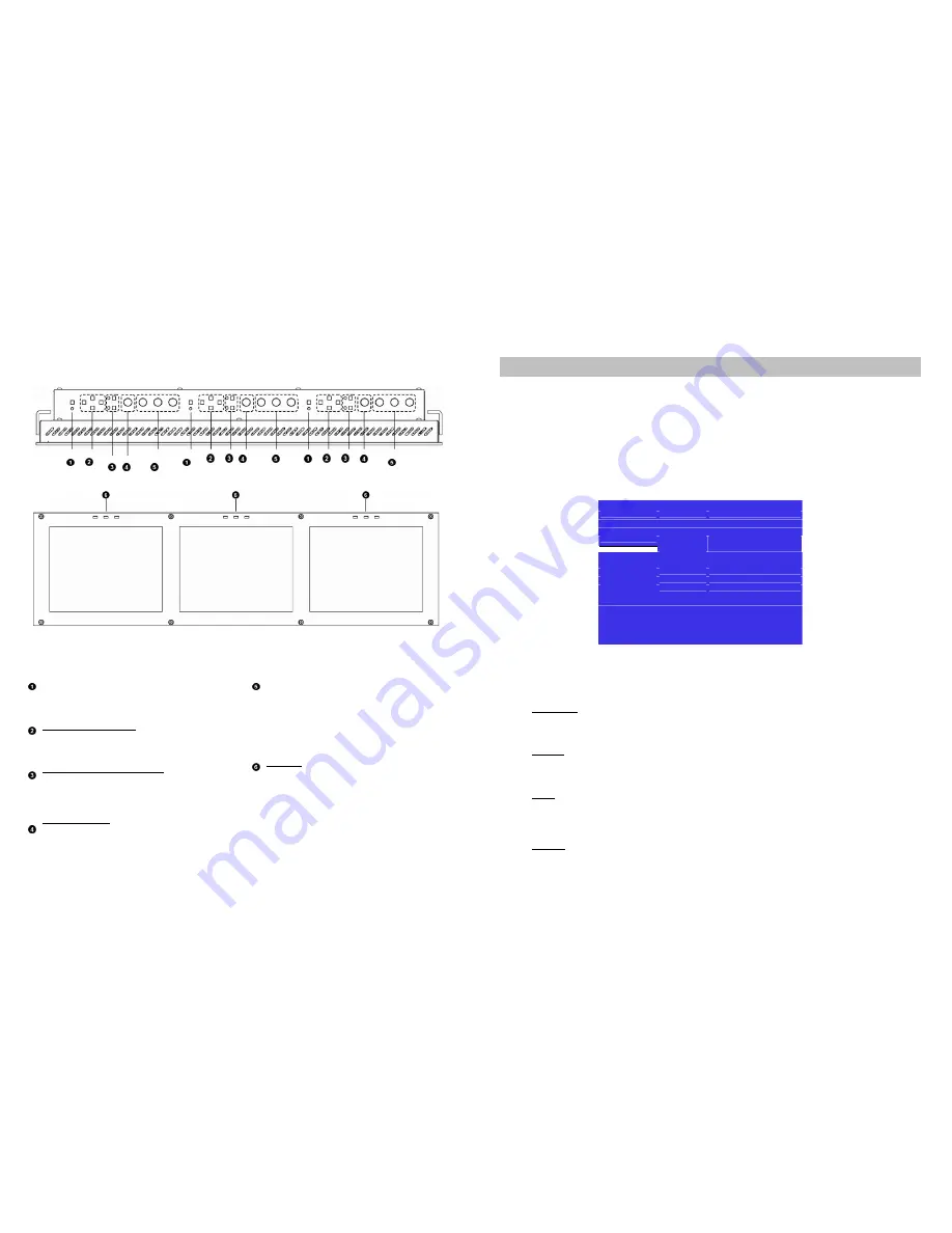
Top and Front Panel Features
On-Screen Menu (continued)
■
Overview
The V-R171-IMD-HDSDI features an In-Monitor Display (IMD) with the ability to display on-screen text and tally in
three colors. IMD text, color, and alignment can be assigned to each screen locally using menu options (see
below). Alternately, IMD text and tally can be remotely controlled via the RS-422/485 serial interface using several
industry-standard protocols, including TSL and Image Video. Multiple V-R171-IMD-HDSDI monitors can be looped
together and each addressed individually via the protocol. All menu features of the V-R171-IMD-HDSDI can also be
controlled via the I-Tech Network Controller box and I-Tech protocol. (Contact I-Tech for additional information).
Use the IMD Configuration submenu to configure various IMD parameters as described below.
Exit
Back
Marker Setup
IMD Protocol
TSL v4.0
Video Config
IM DI D#
001
System Config IMD Group #
001
OSD Config
■
HjilU&liiil-'^K 1
IMD Name(S/N)
IMD Baud Rate
□□□□□□□□□□□□□□□□
38400
IMD Fixed Align
Center
IMD Fixed Color
Red
IMD Fixed Str
DDDDDDDDDDDDDDDD
Tally Source
TSL/I-Tech 422
IMD Tally Mode
Tl
Menu Back/Exit
Select: Select/Deselect
T Up/Increment
4. Down/Decrement
IMD Configuration Submenu
Power Button
Turn the monitor on by pressing the power button. In
the ON state, the LED above the power button will
illuminate green.
Menu Navigation Buttons
Use the
Menu
,
↑
,
↓
, and
Select
buttons to display
and navigate the on-screen menu
(See Main Menu
and Navigation – Page 9)
.
User-Definable Function Buttons
Two user-definable function buttons can be used for
direct access to various settings. Functions are
assigned using the on-screen menu
(See User-
Definable Function Buttons – Page 15)
.
RotoMenu™ Knob
The RotoMenu™ knob is alternate means of
accessing and navigating the main menu, using only
a single control.
Image Adjustment Knobs
Use the image adjustment knobs to adjust color
saturation, brightness and contrast of the image.
The status of each image adjustment parameter is
shown on the bottom left of the screen, with values
ranging from 0 to 100. Pressing each knob resets
the corresponding adjustment to its default setting
(50).
LED Tally
Three LED tally lights (yellow, red, green) are
available above each screen. Each tally light can be
controlled from a variety of sources
(See Tally
Source – Page 21)
.
■
IMD Protocol
Use the IMD Protocol menu option to choose the protocol with which the V-R171-IMD-HDSDI receives remote
commands. Currently, four protocols are available. Contact I-Tech for the latest protocol compatibility.
Image Video
Use the Image Video protocol setting when controlling the IMD from an Image Video tally controller or other
controlling device which utilizes the Image Video protocol. The
IMD #
,
IMD Name
, and
Baud Rate
parameters
must be set for each screen in conjunction with the controlling device.
TSL v4.0
Use the TSL v4.0 protocol setting when controlling the IMD from a TSL tally controller, or other controlling device
which utilizes the TSL v4.0 protocol. The
IMD #
must be set for each screen in conjunction with the controlling
device.
I-Tech
Use the I-Tech protocol setting when controlling the V-R171-IMD-HDSDI using the I-Tech Network Controller box.
This protocol allows remote control of all features on the V-R171-IMD-HDSDI, including marker setup, video
configuration, system configuration, and image adjustments (brightness, contrast, etc.). The
IMD #, IMD Group #,
and
Baud Rate
parameters must be set in conjunction with the Network Controller Box.
I-Tech-IV
This protocol setting accepts Image Video commands via the I-Tech protocol, for use when an Image Video
controller is connected to the I-Tech Network Controller box.
6
19
IMD CONFIGURATION SUBMENU


