Specifications
Power source:
100 to 240 V AC (50 Hz/60 Hz)
Input power consumption:
PU201
PU201
2.0 A (RMS) max for 90 V AC, 1.2 A (RMS) max for 240 V AC
PU201F
PU201F
2.0 A (RMS) max for 90 V AC, 1.0 A (RMS) max for 240 V AC
Output power consumption:
56 V DC: Approx. 1.07 A / 60 W
(Combined output on data pairs and spare pairs.)
Operating environment
Ambient operating temperature: 60 W output: –10 °C to +40 °C {14 °F to 104 °F}
30 W output: –10 °C to +50 °C {14 °F to 122 °F}
Ambient operating humidity:
10 % to 90 % (no condensation)
Strage environment
Storage temperature:
–20 °C to +65 °C {–4 °F to +149 °F}
Storage humidity:
10 % to 90 % (no condensation)
Network:
10BASE-T/100BASE-TX/1000BASE-T, RJ45 connector (×2)
Compliant with IEEE802.3bt/at/af Standard
PU201F
PU201F
Standard SFP module port (LC type) (×1)
AC Input:
IEC320 (C14)
Dimension:
(excluding power cord/cables)
PU201
PU201
65 mm (W) × 36 mm (H) × 163 mm (D)
{2-9/16 inches (W) × 1-13/32 inches (H) × 6-13/32 inches (D)}
PU201F
PU201F
80 mm (W) × 50 mm (H) × 184 mm (D)
{3-5/32 inches (W) × 1-31/32 inches (H) × 7-1/4 inches (D)}
(excluding cord and plag)
Mass:
PU201
PU201
Approx. 300
g
{0.66 lbs}
PU201F
PU201F
Approx. 465
g
{1.03 lbs}
Finish:
PC/ABS resin, Matte black
Standard accessories
Operating Instructions (this document) .......................................... 1 pc.
Power cord (A type) ...................................................................... 1 pc.
<
WJ-PU201P>
Power cord (C type) (BF type) ....................................................... each 1 pc.<WJ-PU201/G><WJ-PU201F/G>
Precautions for installation
This product is designed to be used indoors
This product is not operable outdoors. Do not expose this product to direct sunlight for hours and do not
install the product near a heater or an air conditioner. Otherwise, it may cause deformation, discoloration and
malfunction. Keep this product away from water and moisture.
Equipment classification and power source indication label
Refer to the indication label of this unit for the equipment classification, power source, and other information.
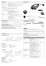
Making connections
PU201
PU201
HUB
Ethernet cable
Ethernet cable
PU201F
PU201F
Technical information website "Compatible SFP modules"
<Control No.: C0504>
HUB
Ethernet cable
Optical fiber cord
Ethernet cable
SFP module
IMPORTANT:
• For the Ethernet cable, use a shielded network cable (STP) CAT5e or higher.
• Make sure that the cable length from the RJ45 network terminal (OUT/DATA PWR OUT) to the camera is
100 m or less.
• When using a splitter, connect it at a point close to the camera, not the PoE Camera Power Unit side.
• Use this unit on a flat table without securing it in place with screws. Do not secure it in place on a ceiling or
wall with screws.
Troubleshooting
Before asking for repairs, check the symptoms with the following table.
Contact your dealer if a problem cannot be solved even after checking and trying the solution in the table or a
problem is not described below.
Symptom
Cause/solution
Reference pages
The PoE Camera Power Unit
does not turn on.
LED indicator
PU201
PU201
and POWER indicator
PU201F
PU201F
do not light or blink.
• Make sure that the power cord is properly connected
to this unit.
• Make sure that the voltage of the outlet is 100 to
240 V AC.
Parts and functions
The camera connected to
the PoE Camera Power Unit
does not turn on.
LED indicator
PU201
PU201
and POWER indicator
PU201F
PU201F
do not light green.
• Make sure that the input Ethernet cable is connected
to the RJ45 network terminal (IN/DATA IN), and
the camera side is connected to the RJ45 network
terminal (OUT/DATA PWR OUT).
• Make sure that the unit and the camera are connected
with a straight network cable of STP CAT5 or higher.
• Make sure that the twisted pair cable or RJ45
connector is not short-circuited.
• If you are using a power splitter, make sure it is
working properly.
Making connections
The camera connected to
the PoE Camera Power Unit
turns on, but a data link is
not established.
LED indicator
PU201
PU201
and POWER indicator
PU201F
PU201F
blink Amber/Green.
• Make sure that the unit and the camera are connected
with a straight network cable of STP CAT5 or higher.
• If you are using an RJ45 Ethernet cable, make sure the
length of the cable from the HUB to the camera is less
than 100 m.
• If you are using a power splitter, make sure it is
working properly.
–
Image data cannot be
transmitted by the optical
fiber cord.
PU201F
PU201F
• Make sure that the SFP module is installed correctly in
this unit.
• Make sure that the connector of the optical fiber cord
is appropriately connected to the SFP module.
• Check if the optical fiber cord appropriately operates
by replacing the optical fiber cord with new one.
–
Parts and functions
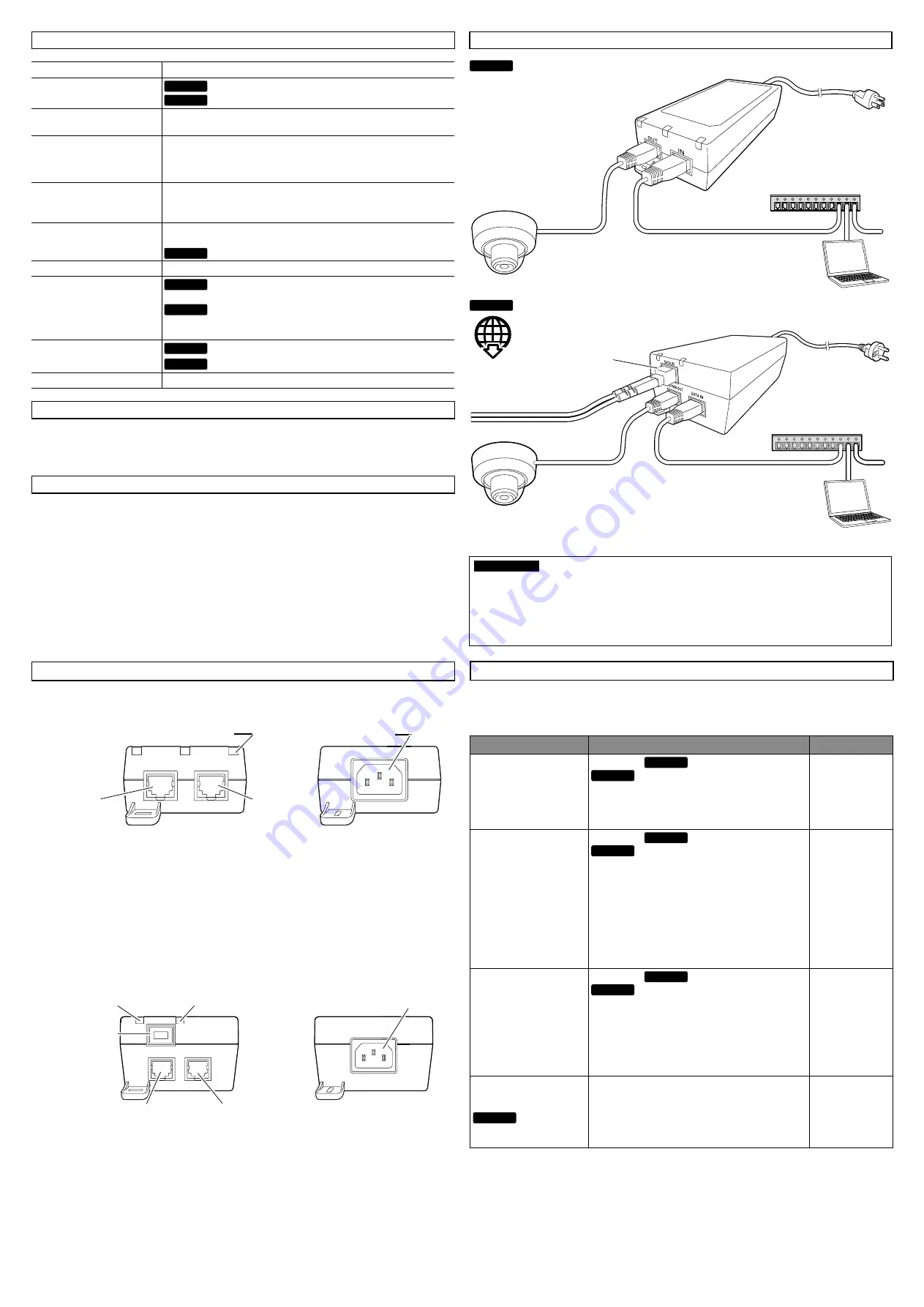
<WJ-PU201P> <WJ-PU201/G>
OUT
IN
LED indicator
AC inlet
RJ45 Network
terminal (OUT)
RJ45 Network
terminal (IN)
LED Indicators
• Power failure
Lights off
• POE power ready but no connection Lights amber short/slow Blinking
• POE output power good
Lights green
• POE detection failure
Lights Amber/Green alternate blinking
• POE output over power or short
Lights amber long/fast blinking
• Invalid load condition
Blinks green
<WJ-PU201F/G>
DATA PWR OUT
DATA IN
DATA IN
AC inlet
RJ45 Network terminal
(DATA PWR OUT)
RJ45 Network terminal
(DATA IN)
PoE indicator
SFP module port
(DATA IN)
POWER indicator
LED Indicators
<
POWER indicator
>
• Power failure
Lights off
• AC Power Good
Lights green
<
PoE indicator
>
• POE power ready but no connection Lights amber short/slow Blinking
• POE output power good
Lights green
• Unit is in Over Load Condition
or Unit has detected an Invalid Load
Lights red


