Hypercable TNS5310-C2P Скачать руководство пользователя страница 7

HYC-TNS5310-C2 QIG V1.0.1


HYPERCABLE sarl    74 Avenue Paul Sabatier ZA de la Coupe 11.100 Narbonne    Tel : +33 (0) 4 68 70 91 75 - cell : 06 82 82 38 73 

Mail : [email protected] - N° SIRET : 384 007 894 00031 – Code TVA CEE: FR90384007894 - 

www.hypercable.fr


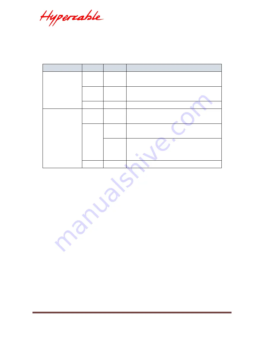
Table 4: Ring Master and Rapid Chain LED 

LED 

Color 

State 

Description 

RM 

(Ring Master) 

Green 

On 

Ring Master has been detected in the 
switch. 

Amber 

On 

Ring Member has been detected in the 
switch. 

-- 

Off 

Disable 

RC 

(Rapid Chain) 

Green 

On 

Rapid Chain has been detected in the 
switch. (Active path) 

Amber 

On 

Rapid Chain has been detected in the 
switch. (Backup path) 

Blinking 

Error: 
There is no correspondent Rapid Chain 
Switch found. 

-- 

Off 

Disable 


Users can check the port status by reading the LED behaviors per the table 
below. 


Содержание TNS5310-C2P

Страница 1: ...HYC TNS5310 C2 QIG V1 0 1 i Quick Installation Guide Of TNS5310 C2P Industrial L2 Managed GbE Switch Sep 2017...

Страница 2: ...HYC TNS5310 C2 QIG V1 0 1 ii Revision History Release Date Revision Release 2017 09 7 V1 0 1...

Страница 3: ...N 1 Overview 1 Front View of the Switch 1 Rear View of the Switch 2 LED Descriptions 2 DIP Switch 6 Reset Button 6 CHAPTER 2 INSTALLING THE SWITCH 7 Package Contents 7 Mounting the Switch on a DIN Rai...

Страница 4: ...user guide describes how to install configure and troubleshoot the TNS5310 C2P 10 Ports L2 Managed GbE PoE Industrial Switch By reading this user guide users can perform the following tasks To check t...

Страница 5: ...View of the Switch Figure 2 Rear panel of the switch LED Descriptions The LEDs on the front panel provide users with switch status checking and monitoring There are three types of LEDs as follows Pow...

Страница 6: ...nctions and descriptions of various LED indicators Table 1 Power LEDs LED Color State Description Power1 Green On The switch is powered ON correctly Off The switch is not receiving power from power1 P...

Страница 7: ...n LED LED Color State Description RM Ring Master Green On Ring Master has been detected in the switch Amber On Ring Member has been detected in the switch Off Disable RC Rapid Chain Green On Rapid Cha...

Страница 8: ...device Otherwise the port may have been disabled through the switch user interface RJ45 Ports Down Green On The port is enabled and supplying power to connected device Amber On An abnormal state such...

Страница 9: ...he Switch to reboot and get the switch back to the previous configuration settings saved Restore the Switch to Factory Defaults to restore the original factory default settings back to the switch Note...

Страница 10: ...talling the Switch Package Contents The Switch Terminal Block Installation Guide Mounting kit Mounting the Switch on a DIN Rail Step 1 Attach the DIN Rail mounting kit to rear panel of the chassis Ins...

Страница 11: ...007 894 00031 Code TVA CEE FR90384007894 www hypercable fr Figure 4 Clip switch to the DIN Rail Step 3 Make sure that the switch is fixed securely to DIN Rail Figure 5 The switch is fixed to DIN Rail...

Страница 12: ...Code TVA CEE FR90384007894 www hypercable fr Figure 6 Attaching Wall Mounting Plates to the Switch Figure 7 The Dimension of Wall Mounting Plates Step 2 Install user supplied screws on the appropriat...

Страница 13: ...ercable fr Step 2 To keep the DC wires from pulling loose use a small flat blade screwdriver to tighten the wire clamp screws on the front of the terminal block connector Step 3 Insert the terminal bl...

Страница 14: ...ng loose use a small flat blade screwdriver to tighten the wire clamp screws on the front of the terminal block connector STEP 3 Insert the terminal block connector prongs into the terminal block rece...

Страница 15: ...4007894 www hypercable fr Installing SFP Modules You can install or remove a mini GBIC SFP module from a SFP port without having to power off the switch Step 1 Insert the module into the SFP port Step...

Страница 16: ...h After changing PC s IP address for example 192 168 1 250 then you can access the Web interface of the switch using the switch s default IP address as shown below The initial switch configuration pro...

Страница 17: ...s button Note Be sure to record all your PC s current IP settings to be able to restore them later Step 6 Select the radio button Use the following IP address and enter in the IP for the PC e g any IP...

Страница 18: ...h as shown by Figure 9 below Figure 11 Web Interface login page If you do not see the above login page please perform the following steps Refresh the web page Check to see if there is an IP conflict i...

Страница 19: ...socket to make sure correct DC source is supplied Port Up Status LED is Off The port is not connected or the connection is not working 1 Check if the cable connector plug is firmly inserted and locke...

Отзывы: