


HYC-TNS5310-C2 QIG V1.0.1
7
HYPERCABLE sarl 74 Avenue Paul Sabatier ZA de la Coupe 11.100 Narbonne Tel : +33 (0) 4 68 70 91 75 - cell : 06 82 82 38 73
Mail : [email protected] - N° SIRET : 384 007 894 00031 – Code TVA CEE: FR90384007894 -
www.hypercable.fr
Chapter 2 Installing the Switch
Package Contents
The Switch
Terminal Block
Installation Guide
Mounting kit
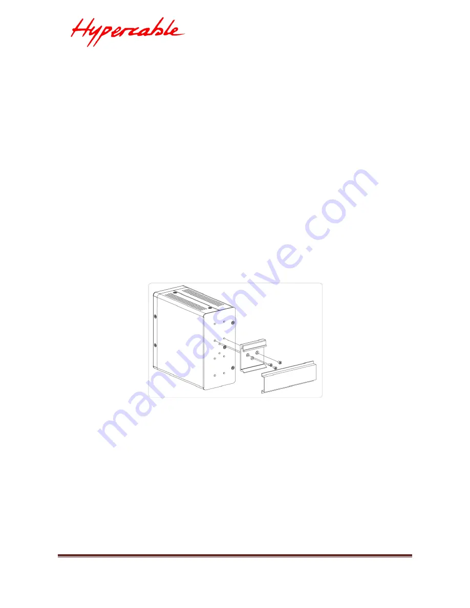
Mounting the Switch on a DIN Rail
Step 1
:
Attach the DIN Rail mounting kit to rear panel of the chassis.
Insert screws and tighten then with a screwdriver to secure the
kit.
Figure 3: Screw DIN Rail Kit to the Switch
Step 2:
Insert the upper lip of the DIN rail into the DIN-rail mounting kit.
And press the switch towards the DIN rail until it snaps into
place.


