


14
6.
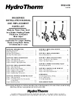
Temperature/Pressure Indicators:
Install in top
holes in front panels; one per module.
7.
Hi-Limits:
Install through knockouts in front panels;
one per module. (Well is factory installed.)
HI-LIMIT AQUASTATS
(FOR EACH MODULE)
TEMPERATURE/PRESSURE
INDICATORS
(FOR EACH MODULE)
FIGURE 5.3
FIGURE 5.2
NOTE: Remember, “A” jacket sets are for enclosing
two modules and “B” jacket sets are for enclosing
three modules.
1. Join upper and lower rear panels with screws pro-
vided.
2. Place front and rear panels along heating plant, and
attach side panel on the right with screws provided.
3. Any number of “A” or “B” jackets may be joined to-
gether in one continuous line; just omit one side panel
(left panel) in between jacket sets. Fasten front and
rear panels to remaining side panel(s) with screws pro-
vided; when assembling, overlap bends as shown.
4. Install top panels starting with left top panel. Lock
each panel into the preceding panel and secure with
the screws provided.
5. Attach rating plate, lighting instructions label and lit-
erature pak where indicated by stencils.
CENTER TOP PANEL
LEFT TOP PANEL
LOWER REAR PANEL
SIDE PANEL
FRONT PANEL
SIDE PANEL
RIGHT TOP PANEL
SIDE PANEL
FRONT PANEL
FRONT PANEL
UPPER REAR PANEL
FIGURE 5.1
SECTION 5: INSTALLING JACKETS


