


TYPICAL PIPING FOR VOLUME WATER HEATING ONLY
(INSTANTANEOUS RECOVERY)
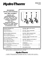
TYPICAL PIPING FOR VOLUME WATER HEATING ONLY
(WITH STORAGE TANK)
NOTE: WHEN A HOLBY MIXING VALVE IS USED THERE MUST BE A 27" DROP BELOW THE COIL COLD WATER TERMINAL IN THE COLD WATER
LINE BEFORE ENTERING THE COIL
*
SHUT-OFF VALVE
City
Water
Supply
Service Hot
Water Supply
Service
Recirculating
Hot Water
BRONZE CIRCULATOR
FLOW CHECK VALVE
EXPANSION
TANK
AIR ELIMINATOR (AIR VENT)
BACKFLOW PREVENTER
MIXING VALVE
*
PRESSURE
REDUCING
(FILL) VALVE
LOW WATER
CUTOFF
MANUAL RESET
HI-LIMIT
THERMOMETER
MAKE-UP WATER METER
FIGURE 3.6
INSTALL MANUAL RESET HI-LIMIT, LOW WATER CUTOFF, AIR ELIMINATOR (ONE OR MORE), EXPANSION
TANK AND BRONZE CIRCULATOR IN LOCATIONS SHOWN. AIR SEPARATOR NOT REQUIRED.
City
Water
Supply
Service
Recirculating
Hot Water
Service
Hot Water
Supply
PRESSURE
REDUCING
(FILL) VALVE
BACKFLOW PREVENTER
BRONZE CIRCULATOR
FLOW CHECK VALVE
SHUT-OFF VALVE
PRESS RELIEF VALVE
STORAGE TANK
AIR ELIMINATOR (AIR VENT)
LOW WATER
CUTOFF
MANUAL RESET HI-LIMIT
EXPANSION
TANK
MAKE-UP
WATER METER
FIGURE 3.7
10
COMBINATION HEATING
& COOLING INSTALLATIONS
If hot water module is installed in connection with water chiller,
chilled water must be piped in parallel with module, using appropri-
ate valves to prevent chilled medium from entering module. When
modules are connected to heating coils in air handling units, where
they may be exposed to refrigerated air circulation, module piping
system shall be equipped with flow-control valves or other automatic
means to prevent gravity circulation of module water during cooling
NOTE:
VALVES "H" OPENED ON HEATING WITH "C" VALVES
CLOSED REVERSE PROCEDURE ON COOLING.
EXP. TANK
VENT
ROOM
UNIT
DRAIN
CHILLER
BOILER
H
C
PUMP
RELIEF
VALVE
FILL
VALVE
DRAIN
C
H
BOILER
FIGURE 3.8


