HydroLynx Systems, Inc.
Model 5033-XX Solar Panel
Page 8
A102759
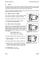
Figure 1
Without Load Test
Figure 2
With Load Test -V
Figure 3
With Load Test - A
4.1
Testing
The tests included in this manual will insure proper solar panel operation and can be used
to troubleshoot a faulty power system. Included in the Drawing section is a schematic for
a solar panel test fixture which will help the technician with these tests.
Remove the panel from the Data Transmitter. These tests must be done on a sunny day
between 9:00 AM and 3:00 PM (solar time).
4.1.1 Without Load Test - Voltage
This checks the regulator’s
charge termination voltage
which keeps the battery from being overcharged.
(Test Fixture Switches: SW1-V, SW2-w/oL, SW3-no)
!
Volt meter is connected as shown in Figure 1.
!
Limit: Manufacture’s specification
4.1.2 With Load Test - Power (watts)
Testing with a Load insures that the panel is able to
supply current to charge the battery. The Load®) is
determined by the minimum battery voltage(V) and the
expected charging current (A); R = V÷A. The resistor
power rating is found by multiplying the current(A) by
the Voltage(V).
e.g. 0.6 A Solar panel:
R=V÷A, R=(12 ÷ 0.6) = 20
S
P=V×A, P=(12 × 0.6) = 7.2 Watts
(Test Fixture Switches: SW1-V, SW2-w/L, SW3-no)
!
Measure Voltage - Volt meter is connected as
shown in Figure 2.
(Test Fixture Switches: SW1-A, SW2-w/L, SW3-no)
!
Measure Current - Current measurement is shown
in Figure 3; the test fixture uses a 1 Ohm sense
resistor and Volt meter to make this measurement.
!
Calculate Power: P = V x A
!
Limit: Manufacture’s specification
Содержание 5033-XX
Страница 10: ......


