background image

2

FILTER MAINTENANCE

FIL1610-1839 / 04.19

2.  Element Replacement

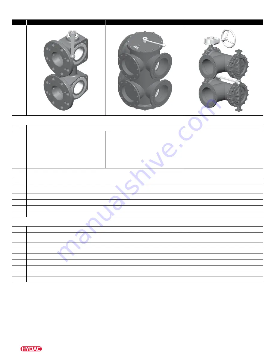
Item

Ball change-over valve "A"

Segment change-over valve "B"

Flap change-over valve "C"

2.1  Element Removal

1.

Check that the ball valve in the filling tube is open. If not, open the ball valve.

2.

Turn lever through 90° – filtration is switched 

to the other side. Close ball valve in the filling 

tube.

Turn lever through 180° – filtration is switched 

to the other side.
Close ball valve in the filling tube.

Signs on the gear shift linkage indicate which 

filter side is currently in operation.
Carefully turn the handwheel to release it from 

the end position and continue to turn it 

(several 

rotations)

 until the other end position 

(filter side)


is reached.
Check the signs on the gear shift linkage once 

again. Close filling tube.

3.

Undo the vent screw on the cover of the filter side that is no longer in operation by a maximum of 1 rotation. Open oil drain plug of filter side no 

longer operating and drain contaminated oil into a suitable container. 

(The oil must not be put back into the system unless it is first cleaned)

.

4.

Loosen cover screws. Lift off cover and remove element holder 

(if present)

.

5.

Pull out filter element.  

Examine element surface for dirt residues and larger particles since these can be an indication of damage to components.

6.

Replace or clean filter element - only W/HC 

(wire screen)

 and V 

(metal fiber)

 elementscan be cleaned.

7.

Clean housing and cover.

8.

Examine filter, especially sealing surfaces, for mechanical damage.

9.

Check O-rings – and replace if necessary.

2.2 Element Installation

1.

Lubricate the sealing surfaces on the filter housing and cover, as well as the O-ring, with clean operating fluid.

2.

When installing a new filter element, check that the designation corresponds to that of the old element. Then lubricate the O-ring in the element 

with clean operating fluid.

3.

Place filter element carefully on to the element nozzle in the housing.

4.

Insert element holder 

(if present)

; re-position cover and screw in cover bolts by hand. Tighten alternately (see TORQUE VALUES).

5.

Close the oil drain plug.

6.

Open the ball valve in the filling tube and fill filter side until oil exits from the vent screw on the cover.

7.

Close vent screw.

8.

Check the filter for leakage.

9.

Leave ball valve in the filling tube in an open position.

NOTE:

Filter elements which cannot be cleaned must be disposed of in accordance with environmental protection regulations.

Содержание RFLD Series

Страница 1: ...lter into the system check that the operating pressure of the system does not exceed the permitted operating pressure of the filter Refer to the type code label on the filter Filters must be flexibly mounted and not installed rigidly to the floor or used as a pipe support When installing ensure that system forces cannot be transferred to the filter A filter with a stand may only be installed to th...

Страница 2: ...er and remove element holder if present 5 Pull out filter element Examine element surface for dirt residues and larger particles since these can be an indication of damage to components 6 Replace or clean filter element only W HC wire screen and V metal fiber elementscan be cleaned 7 Clean housing and cover 8 Examine filter especially sealing surfaces for mechanical damage 9 Check O rings and repl...

Страница 3: ... 1 V 00305932 00305931 2 2 Profile seal ring PI 2 3 O ring 15 x 1 5 3 Lever for change over valve 01205525 Type CAK CAL 00270383 Type CBX 00245759 Type CCV CCW CCX without lever 4 Seal kit E RFLD W 0 Seal kit E RFLD W 0 V 01270496 01271748 01266694 01271749 01269392 01271750 01269393 01271751 01269394 01271752 01269395 01271062 01269424 01271753 4 1 O ring element 97 8x5 33 68 x 5 97 8 x 5 33 2 pc...

Страница 4: ... Indicator Model Code VM 2 B X Indicator Prefix VM G 1 2 3000 psi Trip Pressure 2 29 psid 2 bar standard 5 72 psid 5 bar optional Type of Indicator A No indicator plugged port B Pop up indicator auto reset BM Pop up indicator manual reset C electric switch SPDT D electric switch LED light SPDT Modification Number Supplementary Details Seals omit Nitrile rubber NBR standard V Fluorocarbon elastomer...

Страница 5: ...facturer This is always ensured when using original HYDAC spare parts Keep tools working area and equipment clean After disassembling the filter clean all parts check for damage or wear and replace parts if necessary When changing a filter element a high level of cleanliness must be observed 6 4 Interval Between Element Changes In principle we recommend that the filter element is changed every 6 m...

Страница 6: ...ORATION Mobile Hydraulic Division 1660 Enterprise Parkway Suite E Wooster OH 44691 1 610 266 0100 HYDAC CYLINDERS LLC 540 Carson Road North Birmingham AL 35217 1 205 520 1220 HYDAC TECHNOLOGY CORPORATION HYDAC CORPORATION Sales Office Operations 510 Stonegate Drive Katy TX 77494 1 281 579 8100 HYDAC TECHNOLOGY CORPORATION HYDAC CORPORATION NW Sales Office Operations 1201 NE 144th St Bldg B Suite 1...

Отзывы: