11
HWAM 3120, HWAM 3130, HWAM 3220 (Drawing A)
1.
Recommended for brick wall
10 cm
1.
For inflammable back wall
10 cm
2.
For inflammable side wall
20 cm
1.
To inflammable wall,corner installation
13 cm
3.
Distance to furnishings in front
80 cm
Remember to pay attention to any regulations concerning the required distance between
the wall and smoke pipe.
Requirements for chimney and smoke pipe
The chimney must be of a sufficient height to enable an adequate draft and to prevent smoke problems.
The stove requires a draft of at least 12 Pa.
The chimney must have a minimum opening equivalent to Ø 150 mm. The chimney opening should
always be at least the size of the outlet socket of the stove. The chimney must have an easily acces-
sible soot door.
Smoke pipe and chimney must always be suitable for a stove connection. Ask your HWAM dealer for
more information.
Connection to chimney
All the stoves have both rear and top smoke outlet that can be connected to an approved steel chimney
on top or directly out at the rear to a chimney.
Make sure that the chimney is tight and that no false draft is caused around neither the cover plate,
in connection with a covered smoke outlet, nor the cleanout door and pipe connections. Please note
that bent and/or horizontal smoke pipes will reduce the effect of the chimney draft.
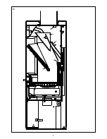
Vertical cross-section of smoke flue (Drawing B and C)
B: Top smoke outlet
C: Rear smoke outlet
• Steel chimney (9).
• Flue gas elbow (10). Fits into smoke flue socket.
• Brick-built jamb of flue (11).
• Built-in pipe sleeve (12). Fits smoke flue.
• Wall rosette (13). Covers disruption to wall around pipe sleeve.
• Joint (14). Sealed with packing material.
• Smoke outlets (15) of the HWAM stove.
• Smoke flue regulating damper (16).
• Soot door (17).
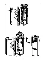
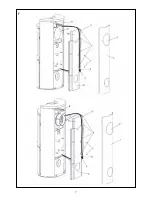
Changing the smoke outlet from top outlet to rear outlet, HWAM 3120 (drawing E)
1. Lift the cast-iron top (1) off the stove
2. Remove the two sides of the stove by loosening the screw (2) and removing it. The two screws
(3) should only be loosened (not removed). Lift the sides off.
3. Open the metallic tabs (4) and take the wires out.
4. Pull the lambda sensor coupling (5) free of the wire fastener (6).
5. Remove the heat shield (7) and wire fastener (6) by removing the two screws (8).
6. Remove the cover plate (9).
7. Remove the flue ring (10) and fasten it to the rear of the stove.
8. Use a soft faced hammer, for instance, to break off the top of the heat shield (11) and the wire
fastener (12).
9. Fasten the heat shield (7) and wire fastener (6) to the stove again.
10. Reposition the lambda sensor coupling (5) in the wire fastener (6).
Содержание 3130
Страница 1: ...User s Manual Instruzoni per l uso GB IT 21 11 2014 97 9658 www hwam com 578 006 3120 3130 3220 ...
Страница 2: ......
Страница 4: ...4 B C A 3 1 1 4 45 4 3 2 1 11 15 14 12 13 9 11 10 17 1 6 5 8 2 3 15 4 16 4 3 14 12 13 ...
Страница 5: ...5 D 6 2 1 3 4 5 ...
Страница 6: ...6 E 13 2 8 4 12 11 6 7 14 1 3 10 9 6 7 8 4 10 11 5 5 1 3 14 6 7 8 4 10 9 11 3 15 5 16 16 17 ...
Страница 7: ...7 F ...
Страница 8: ...8 G ...
Страница 41: ...41 ...
Страница 42: ...42 ...
Страница 43: ...43 ...
Страница 44: ...www hwam com ...

