HW Group IP Relay Скачать руководство пользователя страница 12

IP Relay – 2x relay + RS-232 / Ethernet converter


HW group


June 2006


www.HW-group.com     

      Page 12 / 28 


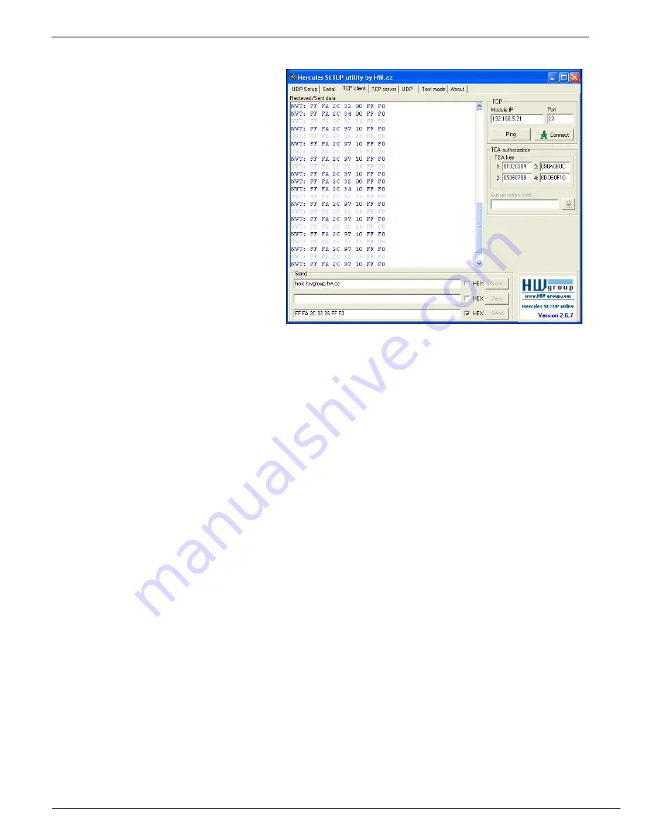
Example of controlling with the Hercules Setup Utility  

For sending the NVT commands you can 
also use our Hercules Setup Utility, 
actually the „TCP client“ tab. For the 
following example we assume you have 
the device connected to the Ethernet 
network and configured according to your 
network parameters – see previous 
chapters. 
 

1.  Click on the „TCP client“ tab 


2.  Make sure that the fields „Module 

IP“ and „Port“ contain correct 
parameters of your IP relay. 
 

3.  Click the „Connect“ button 


4.  Fill the specific field from the 

„Send“ section with the desired 
NVT command with reference to the table from the previous page 
 

5.  Check the field „HEX“ next to the line with the command and press the „Send“ button 


6.  IP relay reacts according to the sent command and responds by the sequence as depicted 


Controllong the red LED using the Hercules Setup Utility 

  Connect to the IP Relay according to the previous chapter (

using the TCP Client mode

)  


  Enter this command into one of the „send“ fields:  

FF FA 2C 32 11 FF F0


Check the 

HEX

 button and send the command using the corresponding button..  


  The red LED will light up and IP relay will respond with:  

FF FA 2C 97 63 FF F0 

Note : The 5th byte (97) can differ according to DIP2 setting. 


  You can turn the LED off using this command:  

FF FA 2C 32 11 FF F0 


  The red LED will turn off and IP relay will respond with:  

FF FA 2C 97 E1 FF F0 

Note : The 5th byte (97) can differ according to DIP2 setting.


* This byte depends on the DIP2 configuration and so it can change. For DIP2=ON is the return 
value 98, for DIP2=OFF it’s 97. 

Содержание IP Relay

Страница 1: ...IP Relay 2x Relay controlled over Ethernet RS 232 Ethernet converter Terminal server EN 900 478a...

Страница 2: ...ntains following items IP Relay in a metal box and mechanic version corresponding to the ordering number A 1 1 serial prolonging cable DB9F DB9M for the device setup via RS 232 Power adaptor in Europe...

Страница 3: ...Virtual Serial Port 10 SETUP troubleshooting 10 Controlling the Relay and LED diodes 11 Setting other parameters of the device 13 HW VSP Virtual Serial Port 15 IPRC IP Relay Control 17 Basic character...

Страница 4: ...lay configuration o Relay 1 Controls breaking contact leading out the power supply output clips can be connected directly as a power supply for an IP camera microwave modem or a power relay o Relay 2...

Страница 5: ...Ethernet The device does not have a WWW interface To control the device you can also use a IPRC program Hercules Utility or programmer examples for JAVA Delphi Borland C Visual Basic PHP and others TC...

Страница 6: ...itching contact remains open when the power supply is turned on NC normally close Break contact remains closed when the power supply is turned on Max load of the contacts max 50V 1A DC Environment par...

Страница 7: ...8 RTS Request to Send 9 unused Note Connector is wired for using the prolong cable with PC check careful connector pinout for your cabling Relay pin descriptions Pin Contact 1 CH1 A 2 CH1 B 3 CH2 A 4...

Страница 8: ...nnector Connect supplied power adaptor to the grid and plug the connector of the power adaptor into the IP Relay s power connector If the power supply is OK the green Power indicator should light up I...

Страница 9: ...e filled with the configured parameters IP address port and the device name if configured 4 Pressing the Use This button will transfer the IP address and port to the Connection section 5 If the requir...

Страница 10: ...ommunication state displayed in the down left corner of the IP Relay s window 6 The Red LED field allows lighting up and turning down the red LED Writing is achieved by a proper Set button Warning The...

Страница 11: ...CLOSES NC Break contact Ch1 OPENS PO Power supply over break contact Ch1 TURNS THE POWER SUPPLY OFF PF Power supply over break contact Ch1 TURNS THE POWER SUPPLY ON FF FA 2C 32 25 FF F0 FF FA 2C 97 D...

Страница 12: ...field HEX next to the line with the command and press the Send button 6 IP relay reacts according to the sent command and responds by the sequence as depicted Controllong the red LED using the Hercule...

Страница 13: ...no matter what port you have choosen for the communication with the device Port 99 is reserved for the TCP setup 3 Press the Connect button The prompt WEB51 should appear in the Received Sent data win...

Страница 14: ...e feeding connector of the IP Relay The green Power indicator should light up The listing of configuration parameters will appear in the Received Sent data window Concrete parameter is set by choosing...

Страница 15: ...r PC Check that NVT is enabled on the UDP Setup tab from Hercules utility If not enable NVT and save the configuration Run HW VSP and search for the IP Relay in the UDP bookmark Choose the MAC address...

Страница 16: ...receives any data switches to the role of a client and opens the connection TCP server s port which is used as input can be configured in main Virtual SP tab and we recommend using numbers higher than...

Страница 17: ...IP relay state Writing the executed operation into a log In the upper left section of the application the list of found devices and their MAC addresses is displayed You can search for the individual...

Страница 18: ...97 31 FF F0 II 19 23 41 192 168 5 21 Read state of relay 2 sent FF FA 2C 32 30 FF FO II 19 23 41 192 168 5 21 State output pins acknowledge received FF FA 2C 97 31 FF F0 II 19 23 45 192 168 5 21 Disco...

Страница 19: ...I Address 192 168 6 200 J Port 23 M Mask 255 255 255 0 G Gateway 192 168 6 254 In IP access filter W Address 0 0 0 0 N Mask 0 0 0 0 X Port 0 0 Y Port Mask 0 0 Active Client Server mode S Send to IP PA...

Страница 20: ...the gateway that provides access to outside networks as defined by the IP address and the mask In IP access filter W Address 0 0 0 0 IP address of a network or computer that is allowed to communicate...

Страница 21: ...IP mode 0 TCP 1 UDP V NetworkVirtualTerminal Off Network Virtual Terminal allows the interpreting of Telnet protocol sequences including certain RFC2217 extensions enabling on the fly changes of seri...

Страница 22: ...w control R RS485 RS422 control Defines idle level of the output RTS pin Important for devices powered from RTS or for add on RS485 Devices that use RTS to switch direction Especially for the internal...

Страница 23: ...hich is requested from the remote side after the connection is established 0 TEA authorisation Off 1 TEA authorisation On K TEA key 0 01 02 03 04 1 05 06 07 08 2 09 0A 0B 0C 3 0D 0E 0F 10 To set the T...

Страница 24: ...port It s actually a decimal formulation of the hexadecimal value of 5 byte controlling NVT command for controlling the IP relay see chapter Selecting sequences for controlling Relay 1 and Relay 2 Yo...

Страница 25: ...the start and stop triggers are equal this value specifies packet length without the 0 4 bytes of start trigger S Start Trigger Pattern 58 0 0 0 Start trigger for packet transmission Four bytes are se...

Страница 26: ...rd to the routine it s possible to enable option K Keep connection which in 10 second intervals sends the NOP command into the open NVT connection Network Virtual Terminal Learn how to use Network Vir...

Страница 27: ...ackets for a DIN molding are available Mounting profiles depending on the ordered version For the descriptions of the variations that can be ordered see the end of this manual L Enclosure has got rubb...

Страница 28: ...sions which differ with contact s configuration as well as with mounting accessories Please check the product website to choose which output configuration and related Ordering ID Purchase number do yo...

Отзывы: