


In Canada, the input rating must be derated by 10 percent for altitudes of 2000 ft to 4500 ft above sea level.
Furnace input rate must be within ±2 percent of input on furnace rating plate.
1. Adjust gas manifold pressure.
a. Remove caps that conceal adjustment screws for gas-valve regulators. (See Fig. 3.)
b. Adjust low-heat input rate manifold pressure for propane gas. (See kit rating plate 326108–201.) Turn low-heat adjusting screw (5/64
hex allen wrench) counterclockwise (out) to decrease input rate or clockwise (in) to increase input rate.
c. Jumper R and W2 thermostat connections on control. (See Fig. 6.) This keeps furnace in high-heat.
d. Adjust high-heat input rate manifold pressure for propane gas. (See kit rating plate 326108–201.) Turn high-heat adjusting screw (5/64
hex allen wrench) counterclockwise (out) to decrease input rate or clockwise (in) to increase input rate.
e. Remove jumper across R and W2 after high-heat adjustment.
f. Replace caps that conceal gas-valve-regulator adjustment screws.
g. Main burner flame should be clear blue, almost transparent. (See Fig. 9.)
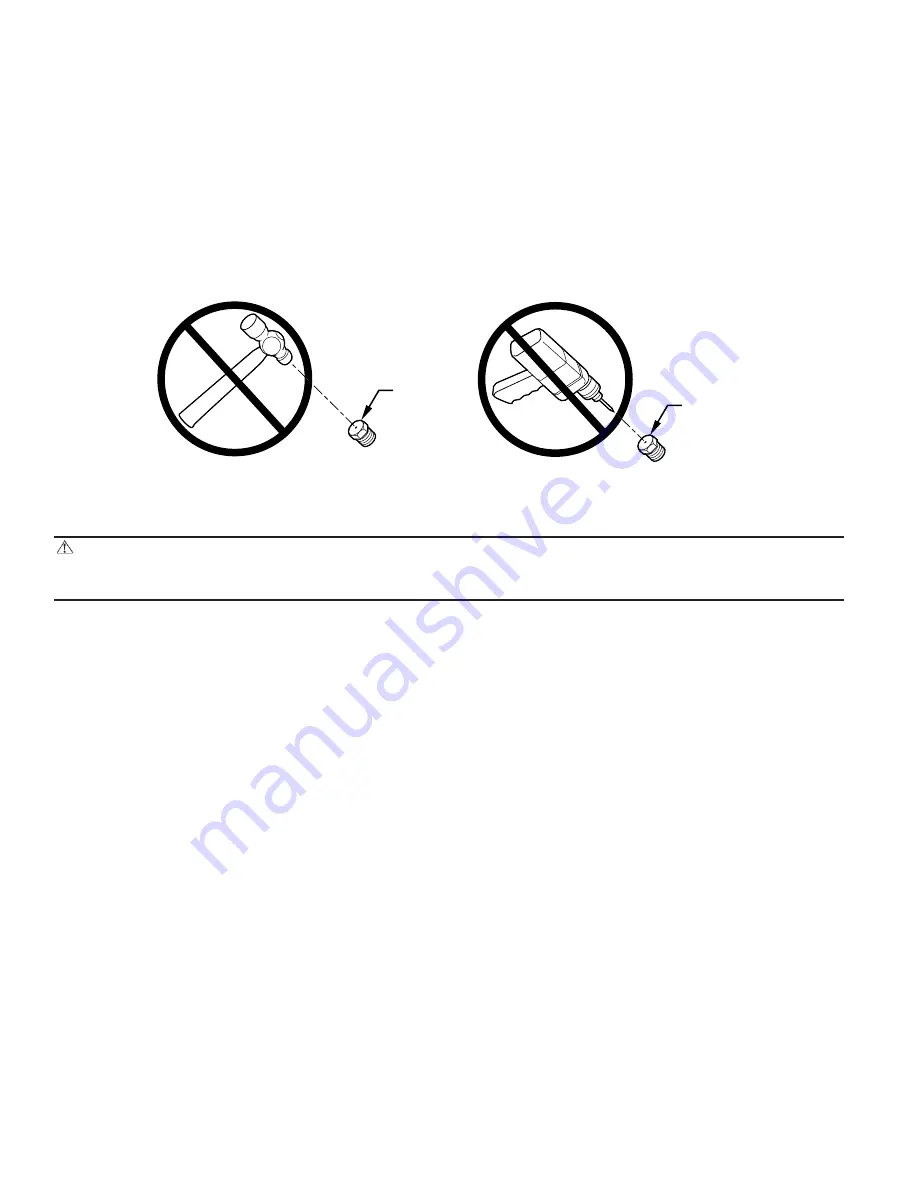
CAUTION: DO NOT redrill burner orifices. Improper drilling (burrs, out-of-round holes, etc.) can cause excessive
burner noise and misdirection of burner flames. This can result in flame impingement of the burners and heat exchangers,
causing failure. Obtain new orifices if orifice size must be changed.
2. Remove jumper across R and W/W1 thermostat connections to terminate call for heat.
3. Turn setup switch to SW-2 to OFF position.
4. Turn furnace gas valve switch to OFF.
5. Turn off furnace power supply.
6. Remove manometer and replace manifold pressure tap plug. (See Fig. 3.)
NOTE:
Use propane-gas-resistant pipe dope to prevent gas leaks. DO NOT use Teflon tape.
7. Turn on furnace power supply.
8. Turn furnace gas valve switch to ON position.
9. Set room thermostat to call for heat.
10. Check pressure tap plug for gas leaks when main burners ignite.
11. Check for correct burner flame. (See Fig. 9.)
12. Observe unit operation through 2 complete heating cycles. See sequence of operation in furnace Installation, Start-Up, and Operating
Instructions.
13. Set room thermostat to desired temperature.
PROCEDURE 8—CHECK LOW GAS PRESSURE SWITCH OPERATION
The newly installed low gas pressure switch is a safety device used to guard against adverse burner operating characteristics that can result from
low gas supply pressure.
This normally open switch closes when gas is supplied to gas valve under normal operating pressure. The closed switch completes control circuit.
Should an interruption or reduction in gas supply occur, the gas pressure at switch drops below low gas pressure switch setting, and switch opens.
Any interruption in control circuit (in which low gas pressure switch is wired) quickly closes gas valve and stops gas flow to burners.
When normal gas pressure is restored, the system must be electrically reset to reestablish normal heating operation.
Before leaving installation, observe unit operation through 2 complete heating cycles. During this time, turn gas supply to gas valve off just long
enough to completely extinguish burner flame, then instantly restore full gas supply. To ensure proper low gas pressure switch operation, observe
that there is no gas supply to burners until after hot surface ignitor begins glowing.
PROCEDURE 9—LABEL APPLICATION
NOTE:
See Fig. 1 or 2 for label location.
A96249
BURNER
ORIFICE
BURNER
ORIFICE
—8—
→
→
Содержание KGANP26012SP
Страница 18: ...18...
Страница 19: ...19...
Страница 20: ...2000 CAC BDP P O Box 70 Indianapolis IN 46206 agganp23 20 Book Tab 1 6a 4 8a Catalog No 63GA NP5...


