background image

Rev.0210

5

SETTING AND  JOINING

The sectional construction of these models enable them
to be joined in line to give the effect of one continuous
display. A joint trim kit is supplied with each joint.

LEVELING

IMPORTANT! IT IS IMPERATIVE THAT
CASES BE LEVELED FROM FRONT TO
BACK AND SIDE TO SIDE PRIOR TO JOIN-
ING. A LEVEL CASE IS  NECESSARY TO IN-
SURE PROPER OPERATION, WATER
DRAINAGE, GLASS ALIGNMENT, AND OP-
ERATION OF THE HINGES SUPPORTING
THE GLASS. LEVELING THE CASE COR-
RECTLY WILL SOLVE MOST HINGE OPERA-
TION PROBLEMS.

NOTE: A. To avoid removing concrete flooring, begin lineup

leveling from the highest point of the store floor.
B. When wedges are involved in a lineup, set them first.

All cases were leveled and joined prior to shipment to
insure the closest possible fit when cases are joined in the
field. When joining, use a carpenters level and shim legs
accordingly.  Case must be raised correctly,  under legs
where support is best, to prevent damage to case.

1. Check level of floor where cases are to be set.

Determine the highest point of the floor; cases will
be set off this point.

2. Set first case, and adjust legs over the highest part of

the floor so that case is level. Prevent damage – case
must be raised under leg or by use of 2x6 or 2x4 leg
brace. Remove side and back leg braces after case is
set.

3. Set second case as close as possible to the first case,

and level case to the first using the instructions in
step one.

4. Apply masking tape 1/8" in from end of case on

inside and outside rear mullion on both cases to be
joined.

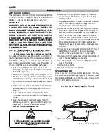
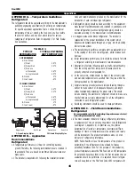
5. Apply liberal bead of case joint sealant (butyl) to

dotted area shown in (Fig.2, #1) of first case.  Apply
heavy amount to cover entire shaded area.
DO NOT USE PERMAGUM!

It is the contractor’s responsibility to install

case(s) according to local construction and

health codes.

6. Slide second case up to first case snugly. Then level

second case to the first case so glass front, bumper
and top are flush.

7. Apply bead of silicone to side of either half of case (if

case is built in two pieces).  Also apply silicone to
seam between overhead light tubes.

8. Slide second half up to first case snugly. To compress

silicone at joint, use two Jurgenson wood clamps to
pull the inside of the bulkheads together. Make sure
case is level from front to back and side to side at
joint. DO NOT USE BOLTS TO DRAW CASES UP
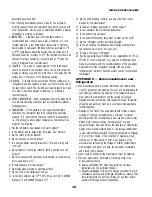
TIGHT! DAMAGE MAY OCCUR!6. Make sure cases
are tight and bolted together in all locations (see
diagram next page). Remove clamps. Cleanup excess
silicone.

9. There may be an interlock system built into the tower,

depending on the height of it. Joining involves a
number of bolts, again dependent on the height.

10. Attach joint trim pieces, that will hide the loose joint

where the case halves come together.

11.Connect case to field electrical, refrigeration, and

pipe to floor sink.

12. Install body covers.
13. Attach cart bumper, if applicable.

SPLASH GUARD
After cases have been leveled and joined, and refrigera-
tion, electrical, and wasted piping work completed, install
the splashguards. Fasten along the top edge, or center, with
#10 X 3/3" sheet metal screws.

 D

O

 N

OT

 S

EAL

 J

OINT

 T

RIM

 T

O

 F

LOOR

!

Installation (cont.)

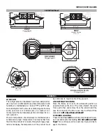
BOLT LOCATIONS

SEALANT APPLICATION

Содержание Chino DBP Series

Страница 1: ...Chino DBP DBRP 01 03 ISLAND PRODUCE REV 0210 Installation Operation Manual DBP DBRP 01 03 ISLAND PRODUCE P N IGIP DBP DBRP 01 03 0210 INSTALLATION OPERATION GUIDE...

Страница 2: ...ossible shortages of mate rial If a shortage should exist and is found to be the re sponsibility of Hussmann Chino notify Hussmann Chino If such a shortage involves the carrier notify the carrier imme...

Страница 3: ...n Ref 6 24 16 26 1 8 DBRP 03 Shown with Optional Ref High Center Divider and Refrigerated Lighted Shelves Scale 3 8 30 Optional Ref High Center Divider and Ref Lighted Shelves Optional Base Display C...

Страница 4: ...etach the walls from each other and remove from the skid Unbolt the case from the skid The fixture can now be lifted off the crate skid Lift only at base of stand EXTERIOR LOADING These models have no...

Страница 5: ...e and outside rear mullion on both cases to be joined 5 Apply liberal bead of case joint sealant butyl to dotted area shown in Fig 2 1 of first case Apply heavy amount to cover entire shaded area DO N...

Страница 6: ...e Store plumb ing system floor drains should be at least 14 off the center of the case to allow use of the P trap pipe section Never use two water seals in series in any one line Double P traps in ser...

Страница 7: ...section of this guide The number of defrosts per day should never change The duration of the defrost cycle may be adjusted to meet conditions present at your location ACCESS TO TX VALVES DRAIN LINES...

Страница 8: ...includes but not limited to Fans Heat ers Thermostats and Lights FIELD WIRING SERIAL PLATE AMPERAGE Field Wiring must be sized for component amperes printed on the serial plate Actual ampere draw may...

Страница 9: ...horten the shelf life of the product 8 Cold coils remove heat and moisture from the case and deposit this as frost onto the coil Thus a defrost is required The only other moisture within the case is t...

Страница 10: ...on loca tions Call for your closest location Ushio America Inc is located at 10550 Camden Drive Cypress CA 90630 T 5 BULBS Please note T 5 lights must be turned off and on after bulb replacement EVAPO...

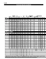
Страница 11: ...1 32 2 4 30 Out 11 2 208 19 0 100 Air 4 3 50 In 230 14 750 18 41 36 50 to Opt Forced 8 x 10 50 min 1 65 3 0 30 Out 11 2 208 19 0 100 Air 5 3 50 In 230 16 750 18 41 36 50 to Opt Forced 8 x 10 50 min 1...

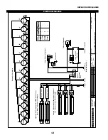
Страница 12: ...roller To Sensors S S MOTOR BALLAST B 232 B B MOTOR MOTOR MOTOR MOTOR MOTOR MOTOR MOTOR MOTOR MOTOR MOTOR MOTOR MOTOR 8 10 12 14 16 18 20 22 24 26 28 30 32 Evaporator Fan Motors Lighted Shelves Option...

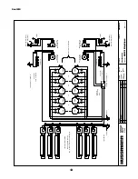
Страница 13: ...l Only dbrp 01k dgn MOTOR MOTOR MOTOR S S To Sensors Case Controller Computer Red 115 230V Black White 115V T Stat Liquid Solenoid Optional Optional Electronic TXV Evaporator Fan Motors MOTOR MOTOR B...

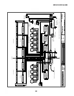
Страница 14: ...Orange Field Connections between both sections S EEPR Valve Optional EEV TXV EEV TXV Optional 10 Case section 12 Case section Light switch in CAD Hussmann Corporation 13770 Ramona Avenue Chino Ca 917...

Страница 15: ...ould perform a complete start up evaluation prior to the loading of food into the refrigerator which includes such items as a Initial temperature performance Coils should be properly fed with a refrig...

Страница 16: ...ASHRAE Standard 72 and ASHRAE Standard 117 12 Are the shelf positions number and size other than recom mended by the manufacturer 13 Is there an improper application or control system 14 Is the evapor...

Страница 17: ...ing handled in processing When a cut or tray of meat is not to be worked on immediately the procedure should call for returning it to refrigeration h Keep tools clean and sanitized Since mechanical eq...

Страница 18: ...IGIP DBP DBRP 01 03 0210 18...

Страница 19: ...nder this warranty shall be limited to a period not to exceed five years from date of factory shipment On Hussmann refrigeration systems an additional 4 year extended warranty for the motor compressor...

Страница 20: ...r particular unit They can be found on a small metal plate on the unit Please note them below for future reference MODEL SERIAL NUMBER Chino Additional copies of thispublication may be obtained by con...

Отзывы: