background image

12

Install Air Tank - Without Wheel Lift

NOTE:

If installing a wheel lift

, refer to "Install Air Tank and Wheel Lift - (for models 

with wheel lift)", page 14.

1.

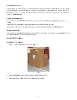
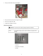
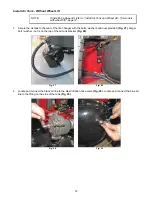
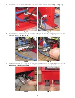
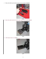
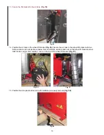
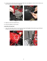
Secure the air tank to the rear of the tire changer with the bolts, washers and nuts provided

(Fig. 27)

. Larger 

bolt / washer / nut is on the top of the air tank bracket

(Fig. 28)

.


Fig. 27                                                                        Fig. 28

2.

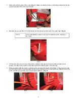
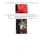
Locate and connect the black air line to the blast inflation hose valve

(Fig. 29)

. Locate and connect the blue air 

line to the fitting on the side of the tank

(Fig. 30)

.


Fig. 29                                                                        Fig. 30

Содержание TCA28

Страница 1: ...y and shorten the life of the tire changer Placement The TCA28 should be placed in a dry area which is not subjected to water spray The TCA28 is best positioned with the back of the unit against a wall Clearance for the operator at the front and left of the tire changer should be at least 3 feet There must also be ample clearance to the right of the tire changer to allow the bead breaking arm to f...

Страница 2: ...e for maximum 12 AMP draw single phase power for the TCA28 Power source requirements of TCA28 are located on the Hunter serial number plate Changes to the AC power cord plug and or power source must be performed by a certified electrician Air Requirements The customer must furnish compressed air at 145 30psi The customer must furnish an air supply line with a 1 4 inch NPT female fitting to connect...

Страница 3: ...llet 6 Remove tire changer from pallet 7 Position the tire changer on the floor Install Column to Base CAUTION The column is heavy and may require two persons to lift safely NOTE The hardware to help secure the column to the base is comprised of the following 2 high nuts 2 long screws all threaded 4 washers ...

Страница 4: ...n the mounting of the column Fig 4 3 Lift the top of the column on top of the rubber covered wheel support and leave it sitting inclined in this position the base of the column points down towards the fixation plate on the housing 4 While one person lifts the column up at its top the second person tends to the bottom of the column to make sure that the air lines are not squeezed and the column slo...

Страница 5: ...re used only to mount the column Fig 7 Fig 7 6 Open the left side cover and finish securing the column with the rest of the attachment hardware NOTE The short air line indicated in Fig 8 with a red piece of tape has to be connected to the back of the cylinder Fig 8 ...

Страница 6: ...n route the air lines into the column Fig 9 NOTE If command unit arm is already installed proceed to Install Side Shovel page 7 Fig 9 2 Position the command unit arm in the upper bracket Fig 10 Secure upper and lower guide screws in the guide screw channels Fig 11 Fig 10 Fig 11 ...

Страница 7: ...nit arm at the pivot point Fig 12 Do not over tighten the screw nut Check that the arm swings freely Fig 12 Install Side Shovel 1 Remove the bolt securing the side shovel pivot pin Fig 13 and lift the pin Fig 14 Fig 13 Fig 14 ...

Страница 8: ... insert the pivot pin Insert the side shovel retraction shaft in the side shovel arm and hand tighten the nut Fig 15 Fig 15 3 Secure the side shovel return spring to the hook on the body side of the side shovel Fig 16 and to the shovel arm Fig 17 Fig 16 Fig 17 ...

Страница 9: ...ve the side shovel completely out so the side shovel retraction shaft and bolt are easily accessible Fig 19 Return side shovel to the in position Fig 20 Fig 19 Fig 20 6 Fully secure the nut to the side shovel retraction shaft using a 32mm socket and an impact wrench Fig 21 Fig 21 ...

Страница 10: ...10 7 Install the plastic side shovel protector Fig 22 Fig 22 Install Bead Press Arm 1 Remove the bolt from the bead press arm pivot point Fig 23 Fig 23 ...

Страница 11: ...ress arm bolt through the bracket and bead press arm and install the washer and nut Fig 24 Fig 24 3 Fully seat the bead press arm bolt and secure with hex head socket cap screw Fig 25 Do not over tighten the bolt nut Check that the arm swings freely Fig 26 Fig 25 Fig 26 ...

Страница 12: ...re the air tank to the rear of the tire changer with the bolts washers and nuts provided Fig 27 Larger bolt washer nut is on the top of the air tank bracket Fig 28 Fig 27 Fig 28 2 Locate and connect the black air line to the blast inflation hose valve Fig 29 Locate and connect the blue air line to the fitting on the side of the tank Fig 30 Fig 29 Fig 30 ...

Страница 13: ... through the upper rear port without grommet Fig 32 Fig 31 Fig 32 4 Position the side panel and secure with hardware previously removed Fig 33 Fig 33 5 Air tank installation is now complete Proceed to Install Side Storage Shelf on page 21 ...

Страница 14: ...g a wheel lift refer to Install Air Tank Without Wheel Lift page 12 NOTE Refer to this illustration when routing air lines Fig 34 TO TOP OF WHEEL LIFT CYLINDER TO MANIFOLD TO BOTTOM OF WHEEL LIFT CYLINDER Fig 34 It may be helpful to mark the air lines as such 1 Remove the filler plate from the pedal area on the front of the tire changer Fig 35 Fig 35 ...

Страница 15: ... pedal assembly near the side of the tire changer Fig 38 Route the wheel lift pedal air lines into the tire changer base Fig 39 Continue routing the air lines above the motor bracket Fig 40 Fig 41 Route them so they are on the belt side of the transmission Not around the back side Fig 38 Fig 39 Fig 40 Fig 41 ...

Страница 16: ...ig 43 5 Route the manifold air line out of the lower rear central port Remove the existing plug and connect the manifold air line Fig 44 Fig 45 Fig 44 Fig 45 6 Position the wheel lift valve and pedal assembly in the front of the tire changer Fig 46 and secure with hardware previously removed Fig 47 Fig 46 Fig 47 ...

Страница 17: ... Remove the inflator pedal protector bracket from the side panel Fig 48 Fig 48 8 Remove the inflator valve from the side panel Remove the foot pedal Fig 49 Fig 49 9 Install the pedal extension Fig 50 Fig 50 ...

Страница 18: ...11 Route the orange air line Fig 52 through the upper rear port without grommet Fig 53 Fig 52 Fig 53 12 Position the wheel lift bracket on the tire changer base Hand tighten the two bolts washers and nuts as shown below Larger bolt washer nut is on the top of the wheel lift bracket Fig 54 Fig 54 ...

Страница 19: ...air tank to the wheel lift bracket with two bolts washers and nuts as shown below Secure all bolts washers and nuts on the wheel lift bracket and air tank bracket Larger bolt washer nut is on the top of the wheel lift bracket Fig 57 Fig 56 Fig 57 15 Position the side panel and secure with hardware previously removed Fig 58 Fig 58 ...

Страница 20: ...es to the top Fig 59 and bottom of wheel lift cylinder Fig 60 Refer to the illustration on page 14 Fig 59 Fig 60 17 Position the wheel lift assembly on the side of the tire changer and secure to wheel lift bracket with 4 bolts provided Fig 61 Fig 62 Fig 61 Fig 62 ...

Страница 21: ...ing on the side of the tank Fig 64 Fig 63 Fig 64 19 Replace the rear air line manifold cover 20 Wheel lift installation is now complete Install Side Storage Shelf 1 Remove the two bolts at the rear corner of the tire changer base Fig 65 Position side storage shelf bracket and secure with bolts previously removed Fig 66 Fig 65 Fig 66 ...

Страница 22: ...ut do not remove the top screws on the side storage shelf bracket Fig 67 Remove the bottom screws on the side storage shelf bracket Fig 68 Fig 67 Fig 68 3 Position the side storage shelf on the bracket Fig 69 Fig 69 ...

Страница 23: ...onto the top of the inflator gauge assembly Secure the inflator gauge bead blast nozzle holder assembly to the side of the storage shelf using two screws as shown Fig 72 TOP SCREW BOTTOM SCREW BEAD BLAST NOZZLE HOLDER INFLATOR GAUGE Fig 72 6 Place the bead blast nozzle in holder Connect red air line to the inflator gauge Fig 73 Fig 73 ...

Страница 24: ...rror and secure with screws previously removed Fig 75 Fig 74 Fig 75 Install Paste Bucket Holder 1 Loosen the two bolts on the paste bucket bracket Slide paste bucket holder onto bracket and secure bolts 2 Secure paste brush holder to the top of the paste bucket bracket Fig 76 Store brush in holder Fig 76 ...

Страница 25: ...striped wire to ground bent blade brown and blue wires connect to X and Y Fig 77 Fig 77 2 Using the supplied wire tie secure the hose retainer to the base of the tire changer Fig 78 Secure such that the hose retainer does not contact the bottom of the column or curl under the inflation tank as the column moves vertically Fig 78 ...

Страница 26: ... 5 Apply air pressure to the tire changer CAUTION Supplied air pressure must not be greater than 220 psi 6 Verify regulated operating pressure is between 110 and 145 psi 7 Verify all controls operate properly NOTE The first time each pneumatic cylinder is used it will operate with sudden jerks After one full travel in both directions the cylinder will operate at normal speed 8 Check for air leaks ...

Страница 27: ...cure both screws Fig 82 Fig 82 13 Place accessories on the tire changer NOTE Always generously lubricate all sides including the bottom of new tool heads with tire lube paste before first use Fig 83 Fig 83 14 Verify operation IMPORTANT After turning on the TCA28 the user must wait 30 seconds for the inverter to learn the position of the rotation pedal potentiometer before operating the tire change...

Страница 28: ...om the tire changer 2 Disconnect the air line from the connection in between the air regulator filter and oiler Fig 84 DISCONNECT THIS LINE Fig 84 3 Plug the open connection on the regulator filter oiler assembly with the appropriate plug NOTE Either an 8mm air line plug such as McMaster Carr part number 51615K194 or a piece of 5 16 x 1 rod steel brass or plastic will work for plugging the open co...

Отзывы: