19
41462-01 10/14/2005
®
Figur
Figur
Figur
Figur
Figure 9d
e 9d
e 9d
e 9d
e 9d
BA
BA
BA
BA
BATTER
TTER
TTER
TTER
TTERY INST
Y INST
Y INST
Y INST
Y INSTALLA
ALLA
ALLA
ALLA
ALLATION
TION
TION
TION
TION
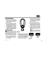
1. Slide the cover off the back of the
remote as shown in Figure 9d,
pressing in and sliding the cover
down to release.
2. Install the included 12 volt alka-
line battery (Type 23A, MN-21 or
equivalent) inside the remote,
matching polarity on the Battery
as indicated by the + and - sym-
bols in the Battery Compartment.
See Figure 9d. Replace the cover.
DIP SWITCH SETTING
DIP SWITCH SETTING
DIP SWITCH SETTING
DIP SWITCH SETTING
DIP SWITCH SETTING
Note:
Note:
Note:
Note:
Note: You will only have to change
the DIP switch settings in the remote
if you are using more than one re-
mote controlled fan in the same area
and want to control them separately.
1. At the circuit breaker or fuse box,
turn the power off for the fan you
want to change.
2. Slide the cover off the back of
the remote and remove the bat-
tery. The battery must be re-
moved when changing dip switch
settings. Refer to BATTERY IN-
STALLATION and Figure 9d.
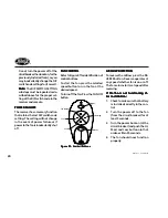
DIP Switch
Set to
01110
DIP Switch
Set to
01001
3. Change the DIP switch settings,
assuring that they are different
from the previously installed fan.
Refer to Figure 9e.
4. Replace the battery and cover.
5. At the circuit breaker or fuse box,
turn the power back on for the fan
whose settings you are changing.
6. Within 20 seconds of restoring
power, push the Hi, Med, and Lo
buttons (in that order). Refer to
Figure 9f.
Note:
Note:
Note:
Note:
Note: You may want to label your
controls to assure you do not mix
them up.
Figur
Figur
Figur
Figur
Figure 9e
e 9e
e 9e
e 9e
e 9e


