17
41462-01 10/14/2005
®
A
A
A
A
ATT
TT
TT
TT
TTACHING THE LOWER
ACHING THE LOWER
ACHING THE LOWER
ACHING THE LOWER
ACHING THE LOWER
SWITCH HOUSING
SWITCH HOUSING
SWITCH HOUSING
SWITCH HOUSING
SWITCH HOUSING
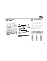
1. Place the lower switch housing
assembly over the upper switch
housing. Make sure that the two
wires for the optional light kit
with wire nuts firmly attached,
are completely inside the lower
switch housing.
2. Align the side screw holes in the
upper and lower switch hous-
ings. Attach the lower switch
housing to the upper switch
housing with three #6-32 x 3/8"
housing assembly screws. See
Figure 8c.
Figur
Figur
Figur
Figur
Figure 8c - Lower Switch Housing
e 8c - Lower Switch Housing
e 8c - Lower Switch Housing
e 8c - Lower Switch Housing
e 8c - Lower Switch Housing
Installation
Installation
Installation
Installation
Installation
Upper
Switch
Housing
2 Wires for
Optional
Light Kit
Lower
Switch
Housing
Housing
Assembly
Screw
INST
INST
INST
INST
INSTALLING
ALLING
ALLING
ALLING
ALLING ACCESSOR
ACCESSOR
ACCESSOR
ACCESSOR
ACCESSORY LIGHT
Y LIGHT
Y LIGHT
Y LIGHT
Y LIGHT
KITS
KITS
KITS
KITS
KITS
To install an optional light kit, replace
the lower switch housing with the
light kit compatible switch housing.
Follow the instructions included with
the light kit for wiring, mounting and
assembly. After completing installa-
tion refer to the fan instructions for
switch housing reassembly.
The following Hunter Low Profile
type light kit models ARE NOT
ARE NOT
ARE NOT
ARE NOT
ARE NOT com-
patible with this fan. DO NOT
DO NOT
DO NOT
DO NOT
DO NOT use
the following models.
22498
22898
22909
26122
26126
26130
27140
27141
27142
27196
28048
29130
26131
26132
26133
26134
26135
26136


