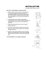
background image

INSTALLATION 

TEST THE INSTALLATION 


TEST THE INSTALLATION 


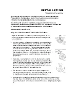
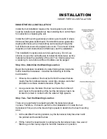
Testing should be performed with the boat in the water, however you can initially 
confirm basic operation with the boat trailered. 


Press POWER once to turn the unit on. There will be an audible chirp when any 
button is pressed to confirm the button press. If the unit does not power-up, 
ensure the unit is fully seated on the mount and that power is available. 
 
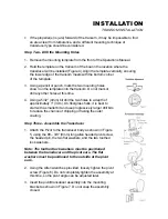
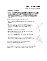
The first screen provides four options: Start-up, Options, Simulator, and 
Diagnostic. A message at the bottom of the screen indicates the transducer 
connection. If no transducer is detected (or one is not connected), the message 
will indicate this and the unit will go into simulator after the initial screen times 
out. 


Note: the transducer must be submerged in water for reliable transducer 
detection. 


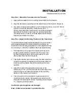
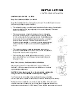
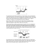
If a transducer is detected, the unit will enter “Start Up” or normal operation 
unless you choose another option. If you do not press any button before the timer 
reaches “0”, the normal operation screen is displayed. If the boat is in water, 
sonar data appears. 


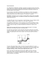
If the bottom is visible on screen with a digital depth readout, the unit is working 
properly. Ensure the boat is in water greater than 2’ but less than the depth 
capability of the unit and the transducer is fully submerged. Remember the sonar 
signal cannot pass through air. 


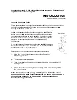
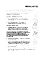
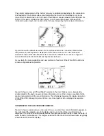
If the unit is working properly gradually increase the boat speed to test high-
speed performance. If the unit-functions well at low speeds but begins to skip or 
miss the bottom at higher speeds, the transducer requires adjustment. Refer to 
the appropriate transducer installation section for more detail. 


Note: it is often necessary to make several incremental transducer 
adjustments before optimum high-speed performance is achieved. 


Important: For Transom Mount transducer installations, install the third mounting 
screw after the final transducer adjustments. 


Humminbird 

 3 Humminbird Lane 

 Eufaula, Alabama 36027 


Содержание Wide 2000

Страница 1: ......

Страница 2: ...our number listed in the Customer Support section INSTALLATION OVERVIEW Your Humminbird fishfinder consists of two primary components to install the control head and the transducer The control head c...

Страница 3: ...should the boat strike debris in the water or when trailering As an alternative to transom mounting it is possible on many fiberglass hulled boats to glue the transducer on the inside of the boat hull...

Страница 4: ...other surface Trolling Motor Mounting The standard transducer can also be adapted to mount on most trolling motors using a different accessory kit This accessory includes a bracket and hose clamp that...

Страница 5: ...minbird fishfinder The installation guide included on the next few pages provides detailed step by step instructions for installation of the control head and transducer For transom mount transducer in...

Страница 6: ...the propeller s This turbulent water is normally confined to areas immediately aft of ribs strakes or rows of rivets on the bottom of the boat and in the immediate area of the propeller s Figure 1 On...

Страница 7: ...g a 5 32 4mm bit drill the two holes to a depth of approximately 1 3cm On fiberglass hulls it is best to start with a smaller bit and use progressively larger drill bits to reduce the chance of chippi...

Страница 8: ...urther adjustment may be necessary to refine the instillation after high speed testing 1 First adjust the pivot angle of the transducer body so its length is parallel with the length of hull of the bo...

Страница 9: ...es or tachometer cable to reduce the possibility of interference If the cable is too short extension cables are available to extend the transducer cable up to a total of 50 15 m Call Humminbird Custom...

Страница 10: ...unting Location Begin the transducer installation by determining where inside the hull to install the transducer Consider the following to find the best location Observe the outside of the boat hull t...

Страница 11: ...The transducer cannot transmit through air The water purges any air from between the transducer and the hull and fills any voids in the coarse fiberglass surface...

Страница 12: ...dry the mounting surface If the surface is excessively rough it may be necessary to sand the area to provide a smooth mounting surface Ensure the mounting area is clear and dry 3 Mix an ample quantit...

Страница 13: ...supplied hole cover The mounting surface should be adequately supported to protect the fishfinder from excessive wave shock and vibration and provide visibility while in operation The mounting area sh...

Страница 14: ...fuse in the connection If you must wire the control head directly to a battery be sure to install an inline fuse holder...

Страница 15: ...mounting surface mark and drill a 1 25mm hole centered between the four mounting holes Figure 22 Note if the cables must pass through the mounting surface at a different location drill the 1 25mm hol...

Страница 16: ...Optional If the cables pass outside the mounting bracket install the hole cover over the hole and fasten in place using the two 8 x 7 8 22mm wood screws Figure 24...

Страница 17: ...ll the excess cable from beneath the mounting surface so the connector holder aligns with the mounting holes on the front of the mounting bracket Figure 27 3 Snap the support plate to the rear of the...

Страница 18: ...rmal operation unless you choose another option If you do not press any button before the timer reaches 0 the normal operation screen is displayed If the boat is in water sonar data appears If the bot...

Страница 19: ...r is connected or detected the Portrait will go into simulator mode after the initial menu screen times out Note The transducer must be submerged in water for reliable transducer detection If the bott...

Страница 20: ...rt up screen after you normally power up the unit When this screen is shown simply press the DOWN ARROW until Simulator is highlighted When the screen times out the unit will be in Simulator mode If t...

Страница 21: ...transducer being used whether or not the Temp Speed sensor is connected and the current setting of various user options See Advanced Operation for information on custom screen options NOTE When in si...

Страница 22: ...s is shown As you learn the many capabilities and user preference functions of the Wide 2000 additional screen configurations are possible Figure D shows a view with Small Digits selected in the User...

Страница 23: ...wave timing Structure is defined as any object physically attached to the bottom The sonar configuration of the Wide 2000 is optimized to give the most accurate depiction of bottom structure possible...

Страница 24: ...ymbols used to indicate the intensity of the sonar return While signal intensity is a good indicator of relative fish size different species of fish have different sonar characteristics so it is not a...

Страница 25: ...ck light With the unit powered on pressing LIGHT once will turn the back light on low Pressing LIGHT a second time will turn the back light on high Press LIGHT again to turn the back light off The bac...

Страница 26: ...which ARROW button has a function in a particular situation Either one or both ARROW buttons can be used to adjust the menu function A hollow ARROW symbol means that the corresponding ARROW button ha...

Страница 27: ...tion of each function for further explanation The one menu option which functions differently than the previously described is the Options menu User Options is a group of functions which are used init...

Страница 28: ...s needed to study a menu press and hold the MENU button and the menu will remain on screen indefinitely If a setting limit is reached the ARROW symbol attached to the menu appears to be hollow which i...

Страница 29: ...to highlight Adjust will allow selection of one of the 9 available ranges Simply press and hold the UP or DOWN ARROW button to scan through the available options If a setting limit is reached the audi...

Страница 30: ...n use the Zoom range is 60 feet It is not possible to use Zoom in conjunction with he Monster Digits view While the Monster Digits view is always available Zoom information is only displayed on the 2D...

Страница 31: ...m is selected the display will appear the same as in Auto Zoom but the zoom range does not change automatically If further adjustment of the Zoom is necessary pressing either ARROW button while Zoom i...

Страница 32: ...gs which correspond to the 3 different size fish symbols shown on screen To enable Fish Alarm Press the MENU button repeatedly until the Fish Alarm menu appears on screen The menu shows two options Of...

Страница 33: ...DOWN ARROW to select Show and the Triplog box will appear at the upper left corner of the screen Triplog provides four pieces of information the distance traveled since the Wide 2000 was powered up or...

Страница 34: ...series of linked menu functions which are used initially to select user preferences Once user preferences are selected it is unlikely that these functions need to be accessed during the normal operat...

Страница 35: ...menu Fish ID The next Option menu is Fish ID There are three selections available Off ID on and ID On The factory setting is ID On With Fish ID Off sonar returns are displayed as raw information There...

Страница 36: ...ransducer The transducer option controls how the Wide 2000 determines which transducer is connected to the unit The Wide 2000 can identify and operate with several different transducers At power up th...

Страница 37: ...transducer selection must be manually changed every time the switch position is changed The Transducer setting is remembered when the unit is powered off If it is not set to Auto a message will appear...

Страница 38: ...start up screen This is a quick way to adjust user options before beginning normal operation Also as mentioned the Options menus are part of the normal menu system and are accessible any time Options...

Страница 39: ...ic to confirm the connections from each transducer If a series of dashed lines is shown then no transducer is connected or there is a problem with the transducer or cable The next categories indicate...

Страница 40: ...6 degree area of coverage The side locking elements can be used independently or together to locate targets near the surface of the water on either side of your boat The Wide Side transducer is availa...

Страница 41: ...ng a trolling motor mount the information displayed is controlled by the direction the trolling motor is pointing not necessarily the direction the boat is traveling To return to normal down operation...

Отзывы: