background image

Chapter 3—Operation                                                                                                                    

3-16  

Hughes-JVC Technology Corporation

MAIN

SOURCES

CH 14 (HDTV)

#      Name

H (kHz)

V (Hz)

I

1

PC

81.1

60

I

2

VGA

31.5

72.0

3

SVGA1

44.5

72.4

4

SVGA2

56.6

60.8

5

HD

33.5

60.2

I

6

PALLD

31.5

50.1

I

7

8514A

34.5

61.1

I

8

VIC 2.1

33.5+

60.2+

I

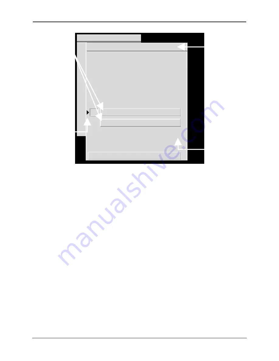
Figure 3.0-5 Active and Highlighted Sources

The Active Source is the source the active channel displays on the screen,
indicated by the lower left pointer under the S

OURCES

 in Figure 3.0-5. The active

source is also displayed on the S

OURCES

 list in the upper right corner of Figure 3.0-

5. The other highlighted sources displayed are additional valid sources for the
highlighted channel (CH 14).

NOTE: Procedures on setting up new sources begin with Section 4.1.on page 4-2.

3.10. Picture Settings

To adjust picture settings:

1.  Select #1, P

ICTURE

 from the M

AIN 

M

ENU

.

2.  Press the number of the selection to be adjusted.

3.  Use the arrow keys to increase or decrease the settings for Brightness,

Contrast, Tint, Color, or Sharpness. Contrast can be adjusted by individual
color by toggling the RGB key to highlight the color desired and using the
up/down arrow keys to adjust. Tint, Color, and Sharpness are not active on
standard RGB VICs.


NOTE: Repeatedly pressing the RGB key toggles from RGB

(all colors on screen) to Red then Green then Blue then back to all colors.

4. The 

B

LACK 

E

NHANCE

 feature enhances black detail in the dark areas of the

image. After selecting the proper levels for the picture settings, select B

LACK

E

NHANCE

 from the P

ICTURE

 menu. Use the arrow keys and select the level

that provides the best black detail in the dark areas of the picture.

Indicates channel
highlighted on the
C

HANNELS

 list (CH 14).

Also shows source in
brackets if this highlighted
channel is also active
(on screen)

If the highlighted channel
indicated here is not the
active channel,
the source is blank.

Highlights show valid

sources for active channel

(CH 14).

Pointer shows active source

for the channel, provided

it is visible on screen.

Pointer is a tilde (~) if source

is an approximate match.

This column shows if
the scan is interlaced
or not ( I = interlaced,
blank = non-interlaced).

Содержание 100

Страница 1: ...USER S GUIDE HJT Model 100 Projector Hughes JVC Technology Corporation 2310 Camino Vida Roble Carlsbad CA 92009 1504 USA 760 929 5300 FAX 760 929 5410 e service hjt com ...

Страница 2: ...1992 IEC 801 4 1988 ANSI C63 4 1992 FCC Part 15 Class A In addition the above product complies with the requirements of the Low Voltage Directive 73 23 EEC and the EMC Directive 89 336 EEC 105826 First Edition December 1997 Confidential and proprietary information Copyright 1997 by Hughes JVC Technology Corporation All worldwide rights reserved This manual was produced by Hughes JVC Technology Cor...

Страница 3: ...2 2 2 3 Projector Orientation 2 4 2 4 Projector to Screen Distance and Alignment 2 5 2 5 Lens Throw Distance and Screen Width 2 6 2 6 Power Requirements 2 9 2 7 Signal Sources Connection 2 9 2 7 1 Terminal or Remote Control 2 10 2 7 2 Infrared IR Windows 2 10 2 8 Sources 2 11 2 8 1 Types of Standard Composite Signals 2 11 2 8 2 Red Green and Blue Analog Signals 2 11 Chapter 3 Operation 3 1 Executi...

Страница 4: ...Bow 4 12 4 3 4 Skew Rotate G 4 13 4 3 5 Linearity G 4 14 4 3 6 Edge Linearity 4 16 4 3 7 Keystone 4 17 4 3 8 Pincushion 4 18 4 3 9 Centering Red and Blue 4 19 4 3 10 Linearity R and B 4 19 4 3 11 Skew Rotate R and B 4 20 4 3 12 Projection Lens Focus Fine 4 20 4 4 CRT Focus and H V Dynamic Focus 4 21 4 5 ILA Sensitivity and Bias 4 21 4 6 Convergence XY Registration 4 23 4 6 1 Purpose of Convergence...

Страница 5: ... 1 Cleaning the Cabinet 5 1 5 1 2 Cleaning the Projector Lens 5 2 5 1 3 Air Filters 5 2 Chapter 6 System Specifications Image Quality 6 1 Input Compatibility 6 1 Inputs 6 1 Control Ports 6 1 Operating Parameters 6 2 Installation 6 2 Accessories included 6 2 Accessories optional 6 2 Appendix A Extron Switcher Interface to Model 100 Appendix A 1 Appendix B Configuration Data Export Import Procedures...

Страница 6: ...Table of Contents vi Hughes JVC Technology Corporation ...

Страница 7: ...ect the interference at their expense Use shielded interconnect cables with this equipment to insure compliance with the pertinent RF emission limits governing this device 0 1 Warnings and Cautions Thoroughly read and follow all Warning and Caution statements in this manual Warning and Caution definitions are as follows WARNING SYMBOL Warns user of a potential electric shock hazard in a procedure ...

Страница 8: ...hin the system and must be vented to keep the system running Blocking air intake or exhaust ports could cause the projector to overheat Do not enclose the unit in a restricted space refer to physical access and thermal clearance illustration guidelines If a foreign object falls inside the projector immediately unplug the projector and call a Hughes JVC certified technician for object removal CAUTI...

Страница 9: ...Amp single phase 50 60 Hz AC power source VERIFY THAT LOCAL POWER SOURCE MATCHES THESE REQUIREMENTS BEFORE OPERATION Installation should be performed by an electrician with knowledge of current electrical codes in the country of use For continued safe and reliable operation only use cables supplied by the manufacturer for power and signal connections ...

Страница 10: ...Safety Information x Hughes JVC Technology Company ...

Страница 11: ...ntenance Access 2 2 Physical Dimensions 2 3 Projector Orientation 2 4 Projector to Screen 2 5 Lens Throw Distance 2 6 Power Requirements 2 7 Signal Sources Conn 2 7 1 Terminal or Remote 2 7 2 Infrared IR Window 2 8 Sources 2 11 2 8 1 Types of Standard C 2 8 2 Red Green and Blue 2 8 2 1 Signal Inputs 3 0 Operation 3 1 Executive Remote 3 2 Technician Remote 3 3 Power ON and OFF CAUTION Before applyi...

Страница 12: ...rce 4 2 Timing Settings and 4 2 1 Clamp Type 4 9 4 2 2 VTR Mode 4 9 4 2 3 Blanking 4 10 4 2 4 Phase 4 10 4 3 Geometric Adjustme 4 3 1 Centering G 4 3 2 Size4 11 4 3 3 Bow4 13 4 3 4 Skew Rotate G 4 3 5 Linearity G 4 16 4 3 6 Edge Linearity 4 3 7 Keystone 4 18 4 3 8 Pincushion 4 19 4 3 9 Centering Red and 4 3 10 Linearity Red and Blue 4 20 4 3 11 Skew Rotate Red and Blue 4 21 4 3 12 Projection Lens ...

Страница 13: ...ifier assembly The projector is intended to be used for the projection of video and graphics as shown in this manual It should not be used for purposes it was not designed for 1 1 Shipping and Inspection The projector is shipped in a standard shipping container which is not reusable A reusable container is optional and recommended if the projector is moved and shipped often The containers are equi...

Страница 14: ...cs Enhancer RGBHV Quad RGBHV Video Mux multi port Component HDTV YPbPr Input Module Quad Standard Decoder Module with Line Doubler Projection Lenses Motorized Zoom 3 1 8 1 lens Fixed 1 1 Wide Angle lens Used for short projection distances and rear projection applications Fixed 1 5 1 lens with offset Needed for ceiling mounted applications or where wider projection angles are necessary Tethered Tec...

Страница 15: ...to Figure 1 0 1 on page 1 5 Figure 1 0 1 Top View Left Right Designation Table 1 0 1 Acronyms Used In Manual Acronym Explanation CH Channel CRT Cathode Ray Tube HDTV High Definition Television HVPS High Voltage Power Supply ILA Image Light Amplifier IR Infrared LVPS Low Voltage Power Supply PCB Printed Circuit Board PC Personal Computer RGB Red Green Blue UV Ultraviolet VIC Video Input Card VNR Vi...

Страница 16: ...Chapter 1 Introduction 1 6 Hughes JVC Technology Company ...

Страница 17: ... ventilated and the projector air intakes and exhausts should not be blocked in any way 2 1 1 Air Flow The HJT Model 100 Projector dissipates 4 100 BTUs hr and must not be placed in an enclosure that would limit air flow Adequate ventilation is necessary to provide proper air flow to prevent overheating For optimum operation maintain the following air flow clearances around the projector for prope...

Страница 18: ...asure from Metric Standard Top of projector 30 5 cm 1 foot Around the projector sides 61 0 cm 2 feet 2 2 Physical Dimensions The illustrations in this section show the footprint and physical dimensions of the HJT Model 100 Projector Figure 2 0 1 Top View M100 Projector dimensions in mm Figure 2 0 2 Bottom View M100 Projector dimensions in mm Projector Centerline 511 2 558 8 Projection Lens Centerl...

Страница 19: ...Chapter 2 Installation HJT Model 100 User s Guide 2 3 Figure 2 0 3 Right Side View M100 Projector dimensions in mm 897 2 14 1 35 1 911 3 ...

Страница 20: ...g elements before installing the Model 100 to optimize the layout of the theater meeting room or projection booth Projector to Screen distance and alignment Screen size View seating arrangements Lens type selection refer to Figure 2 0 8 on page 2 8 Physical access see Table 2 0 2 on page 2 2 Heat dissipation see Table 2 0 1 Air Flow Clearances on page 2 1 Table or ceiling mounting 15 5 74 3 118 4 ...

Страница 21: ...om lens The maximum projector to screen vertical tilt angle for a table or ceiling mount is 15º vertical Any tilt greater than 15º will result in a severe keystone error that cannot be corrected by the Keystone adjustment The HJT Model 100 Projector can be used upright or downright at any angle from 5 to 85 Figure 2 0 5 Maximum Projector to Screen Vertical Tilt Angle for table mounting front or re...

Страница 22: ... 48 meters 18 feet as illustrated in Table 2 0 4 Table 2 0 4 Throw Distance Calculation Screen Width x Lens Ratio Throw Distance 3 65 meters x 1 5 5 48 meters 12 feet x 1 5 18 feet A pictorial illustration of throw distance and screen width is shown in Figure 2 0 7 A graphical model is shown in Figure 2 0 8 on page 2 8 Refer to these figures for calculating the throw distance required using the di...

Страница 23: ...on 3 1 1 1 lenses NOTE Refer to the HJT Series 100 Projector Service Manual or the HJT Series 100 Projectors Projection Lens Installation Guide shipped with the lens when changing from the Zoom lens to a fixed lens or from a fixed lens to the Zoom lens Lens installation must be performed only by HJT Certified Technicians 10 97 meters 36 feet 3 65 meters 12 feet Screen Width 3 65 meters 12 feet 3 1...

Страница 24: ... 1 5 1 1 1 Throw Distance dimensions are in meters Figure 2 0 8 Lens Pattern for Model 100 The Zoom lens can be used for any screen width and throw distance points that fall inside the shaded zoom lens outline Zoom lens numbers represent the ratio of throw distance to screen width A throw distance of 20 and a screen width of 4 is indicated by the in the shaded area of the chart Screen Width meters...

Страница 25: ...tor Installation should be performed by an electrician with current knowledge of electrical codes in the country of use A qualified electrician must be utilized if custom power applications are necessary Hughes JVC will not be responsible for any hazards caused by unlicensed personnel changing the original single phase 3 wire design power connection 2 7 Signal Sources Connection There are two 2 ba...

Страница 26: ...ions through the menu tree but also provides access to setup functions instantly by keys on the remote instead of navigating through the menu tree Either remote can be used with a tether or as infrared Drawing of the keys on the remotes and explanations of the key functions are detailed in Figure 3 0 1 Executive Remote Control Figure 3 0 2 Technician Remote Control and Table 3 0 1 Remote Control K...

Страница 27: ...Projector can display NTSC PAL SECAM and RS170 video only through the Quad Standard Decoder Module with Line Doubler VIC option or via an External Scan Converter Line Doubler or Quadrupler 2 8 2 Red Green and Blue Analog Signals The most common input is separate red green and blue RGB analog signals The sync signals for RGB analog sources can be separate horizontal and vertical composite horizonta...

Страница 28: ... Corporation Comm Setup see Section 3 6 on page 3 8 about Navigating the Menu in reference to video switchers If using a communications controller such as an AMX or Crestron connect it to either port A or port B Use only one 1 controller per projector ...

Страница 29: ... supplied with the projector Both remotes perform the same functions when operated through the menu tree This chapter assumes the projector is being operated using the Executive Remote control 3 1 Executive Remote The Executive Remote Control can be used as an infrared or tethered remote see Figure 3 0 1 on page 3 2 If using the Executive remote as an IR do not plug in the tether cable If using wi...

Страница 30: ...Chapter 2 Installation 3 2 Hughes JVC Technology Corporation Figure 3 0 1 Executive Remote Control Descriptions of key functions can be found in Table 3 0 1on page 3 5 ...

Страница 31: ...via the menu structure and save time during set up The Technician Remote can be used as an IR remote or with a tether like the Standard Remote An 8 meter tether cable is provided with the Technician Remote Inserting the tether cable disables the IR transmitter See Figure 3 0 2 on page 3 4 for an illustration of the Technician Remote control keys and Table 3 0 1 on page 3 5 for key function and usa...

Страница 32: ...Chapter 2 Installation 3 4 Hughes JVC Technology Corporation Figure 3 0 2 Technician Remote Control Descriptions of key functions can be found in Table 3 0 1on page 3 5 ...

Страница 33: ...ay Toggles on screen display ON OFF RGB Color selection to adjust or hide Toggle to desired color Hide Blanks CRTs for all colors or selected color Toggles video or selected color on or off Lin Horizontal and Vertical Linearity correction for improper grid spacing on an image Press LIN Left Right or Up Down arrows to correct linearity distortion Edge Lin Edge Linearity Horizontal and Vertical edge...

Страница 34: ...ughes JVC logo may appear on the screen for five 5 seconds The screen then displays the external video or goes blank if no video signal is present 5 NOTE Hughes JVC logo is a default setting Access PREFERENCE MENU to deselect if desired 3 4 Displaying Internal Test Patterns As a quick way to make sure that the projector is working correctly the HJT Model 100 Projector has nine 9 internally generat...

Страница 35: ... the name and characteristics of these sources by selecting MENU and then selecting CHANNEL Table 3 0 3 shows the on screen display of the factory preset channels menu Table 3 0 3 On Screen Factory Preset Channel Menu Display CHANNELS CH 1 INT Name VIC Sources 1 Facto 1 1 VGA XGA SXGA 81 1kHz 2 3 4 Table 3 0 4 defines designations displayed in Table 3 0 4 Table 3 0 4 Factory Preset Channels Menu D...

Страница 36: ... keep it intact for future then use Backing up Settings procedure on page 4 38 To use a factory preset source file 1 Highlight the channel with the desired source file and attach it to the highlighted channel see Section 3 8 on page 3 12 2 Note that any adjustments to the attached source will also alter the data from the original factory source file 3 5 1 Internal Source Every channel has a preset...

Страница 37: ...r select PREFERENCES at the SYSTEM MENU 4 From PREFERENCES select NUMBERED MENUS and press ENTER to toggle the NUMBERED MENUS box to select menus with or without numbers checked box menus with numbers 3 6 3 To Choose Full or Short Menus Full menus are necessary to perform timing geometry convergence and maintenance Short menus allow very limited menu selections such as picture settings and channel...

Страница 38: ...hen in the SYSTEM menu 7 above first example to go to 4 TIMING above second example press the left arrow three 3 times to move three 3 places to the left To move back to the SYSTEM menu press the right arrow three 3 times During setup adjustments this feature can save time when moving between Picture Timing Geometry and Convergence To select a Video Switcher 1 Under MENU SETUP Port A or Port B dev...

Страница 39: ...tatus 2 Display System Error log 3 Reset System Error log 4 Export Configuration 5 Import Configuration 6 Reset Lamp Timer 5 GEOMETRY 1 Size 2 Centering 3 Keystone 4 Pincushion 5 Bow 6 Skew Rotate 7 Linearity 8 Edge Linearity 9 Reg Enable 9 DIAGNOSTICS 1 Display Error Log 2 Reset Error Log 3 PREFERENCES 1 Numbered Menus 2 Display Logo 3 Shutters on Hide 4 Focus Enable 7 SYSTEM 1 Test Patterns 2 Pr...

Страница 40: ...urce files using one 1 specific VIC switch number set up to accept up to 20 sources with different parameters such as horizontal and vertical scanning rates interlaced noninterlaced scanning sync levels A channel defines the input path for a source Source A specific input format such as VGA HDTV NTSC etc with a given set of parameters such as horizontal and vertical scanning rates interlaced nonin...

Страница 41: ...ight the selected channel Press ENTER again to activate the highlighted channel If using arrow keys scroll to highlight the desired channel and press ENTER once 5 If the active channel contains more than one 1 source file for the incoming video source the closest match will be automatically selected NOTE If the channel number is known it may be selected by pressing the channel number then pressing...

Страница 42: ...nel to show the source type 4 Selects the VIC slot and or VIC port to handle that source if the projector uses an optional or a multi port VIC 5 Follows the adjustment procedures in Chapter 4 on page 4 37 to set up a source file to handle that specific source Once a source has been set up it can be attached to another channel To attach a source means that an original source file and its geometry a...

Страница 43: ...s starting points to set up new sources in other channels The first channel may be copied to a second channel Follow the procedure in Section 4 10 on page 4 38 about Backing up Settings The channel groups of source files can be customized to suit whatever purposes are needed Each channel is capable of handling up to 20 different sources There are 99 channels groups of source files available The ma...

Страница 44: ...Color or Sharpness Contrast can be adjusted by individual color by toggling the RGB key to highlight the color desired and using the up down arrow keys to adjust Tint Color and Sharpness are not active on standard RGB VICs NOTE Repeatedly pressing the RGB key toggles from RGB all colors on screen to Red then Green then Blue then back to all colors 4 The BLACK ENHANCE feature enhances black detail ...

Страница 45: ... to enhance black detail 7 VIC SETTING Video Input Card settings 2 CHANNELS Displays the channel numbers channel names VICs and some of the sources attached to each channel Pressing M MODE provides the following sub menu for editing purposes 1 EDIT Allows editing of the channel name and VIC Right and left arrows move the cursor to the point for editing pressing enter chooses the field to edit up d...

Страница 46: ...efault is back porch 5 VTR MODE Toggle for VTR ON or OFF Default is OFF 5 GEOMETRY Displays the following raster adjustments 1 SIZE Value adjustment for width and height All Coarse R B Fine 2 CENTERING Value adjustment for red green and blue horizontal and vertical centering 3 KEYSTONE Value adjustment for left right top and bottom keystone correction 4 PINCUSHION Value adjustment for left right t...

Страница 47: ...ESET Menu for Registration Threshold and Sensitivity Resets Registration to 128 Threshold to 128 and Sensitivity to 128 It is also color selectable 7 SYSTEM Displays the SYSTEM MENU and its six 6 submenus as shown below 1 TEST PATTERN Provides selection of nine different test patterns as described in Chapter 3 2 PROJECTION LENS Value adjustment for zoom and focus 3 PREFERENCES Allows operator to s...

Страница 48: ...S Red green and blue ILA light valve bias adjustment Must be done whenever light valve components are replaced or ILA Sensitivity is changed 2 ILA SENSITIVITY Value adjustment for light valve bias frequency 3 CRT FOCUS Value adjustment for R G or B CRT focus 4 H V DYNAMIC FOCUS Value adjustment for horizontal and vertical dynamic focus 6 MAINT UTILITIES Provides a submenu below for maintenance pur...

Страница 49: ... turns FULL MENUS ON Is the default setting 3 12 Short Menu Structure Short menus allow very limited menu selections and prevent inadvertent changes in setup data when several operators are using the remote To use short menus 1 Press MENU to display the MAIN MENU 2 From the MAIN MENU select MAIN MENU SHORT VERSION 1 PICTURE 2 CHANNEL 3 SAVE CHANGES 4 FULL MENUS 1 PICTURE 2 CHANNELS 1 BRIGHTNESS Na...

Страница 50: ...ect DEC VT 100 ANSI may already be selected 4 Use a Null Modem cable to connect between the projector and the terminal 5 Refer to Section 3 13 1Terminal Preferences and 3 13 2 Communications Protocol for WINDOWS setup 3 13 1 Terminal Preferences Select SETTINGS again from the menu bar Select TERMINAL PREFERENCES Set the modes as indicated in Table 3 0 8 below Table 3 0 8 Terminal Preferences Modes...

Страница 51: ... Command Equivalents Action Keyboard Input Standard Remote Keys Technician Remote Keys Decimal Hex Power OFF All CTRL F 6 6 Power ON All CTRL U 21 15 Power ON OFF CTRL P Power Power 16 10 Power ON OFF Electronics only CTRL E 5 5 Power ON OFF Lamp CTRL L 12 0C Left Arrow Left Arrow Left Arrow Left Arrow 27 91 68 1B 5B 44 Right Arrow Right Arrow Right Arrow Right Arrow 27 91 67 1B 5B 43 Up Arrow Up ...

Страница 52: ...ew 87 57 Threshold D Thresh 68 44 Sensitivity V Sens 86 56 Registration G XYReg 71 47 Redraw Terminal Screen 124 7C Reboot CTRL Shift _ 49 31 Restart System Software CTRL Shift 48 30 The ARROW KEYS are a sequence of Decimal or Hex numbers representing the sequence of ESCAPE LEFT BRACKET and A B C or D depending on which arrow was pressed The first number represents the ESCAPE key the second number...

Страница 53: ...ty R and B 4 19 4 3 11 Skew Rotate R and B 4 20 4 3 12 Projection Lens Focus Fine 4 20 4 4 CRT Focus and H V Dynamic Focus 4 21 4 5 ILA Sensitivity and Bias 4 21 4 6 Convergence XY Registration 4 23 4 6 1 Purpose of Convergence 4 23 4 6 2 Cursor Shapes and Sizes 4 23 4 6 3 Convergence Profiled 4 24 4 7 Black Level G2 and Sensitivity Offset 4 29 4 7 1 Black Level G2 4 29 4 7 2 Sensitivity Offset 4 ...

Страница 54: ... finished Red and Blue is then centered to match Green and converged onto Green in the Convergence procedures To hide Red and Blue toggle the RGB key to RED press HIDE then toggle to BLUE and press HIDE Green is now the only color displayed on the screen Toggle the RGB KEY to highlight G To avoid redundancy in the procedures in this chapter some general information instructions phrases and definit...

Страница 55: ...Chapter 4 Setup Adjustments HJT Model 100 User s Guide 4 3 ...

Страница 56: ...E box under the SYSTEM PREFERENCES menu is checked Checking this box activates the shutter mechanism to hide the ILA images and provides easier more accurate settings of these adjustments On single axis adjustments such as PICTURE SETTINGS G2 THRESHOLD SENSITIVITY ILA BIAS etc up down arrow keys are shown on the screen left right arrow keys though not shown will also accomplish the same adjustment...

Страница 57: ...gh For the Timing and Geometry setup procedures below it is necessary to obtain a rough focus of the Projection Lens in order to read menus and do the adjustments If the focus is adequate to read the menus this procedure can be skipped until after the Timing and Geometry adjustments are finished When the Timing and Geometry adjustments are complete and prior to starting convergence the Projection ...

Страница 58: ...he MAIN MENU 2 From the CHANNELS list select a new channel number by pressing the channel number and ENTER This highlights the channel for editing purposes but does not make it active The channel can also be highlighted with the arrow keys 3 Press MODE This brings up a submenu for editing this is a toggle key Pressing MODE again removes the submenu 4 Use the up down arrow keys to select EDIT and p...

Страница 59: ...the SOURCES list that can be edited is the source name All other columns and items are sensed by the projector and added automatically when the source is received 15 Press the left arrow key to move back to the CHANNELS list Verify that the new source is listed in the highlighted Channel MAIN CHANNELS CH 3 SVGA2 Name VIC Sources 1 VGA 2 1 LDNT 2 RGB 1 1 LD 3 SVGA 2 1 VGA SVGA1 SVGA2 4 MAC 2 2 MAC3...

Страница 60: ...el 1 Table 4 0 2 Channel 1 Factory Preset Sources Channel 1 Factory Preset Sources 31 5 kHz 48 kHz 64 kHz 81 1 kHz NOTE Any adjustments to the attached source will also alter the data from the original factory source file To use a factory preset source file and keep it intact for future use copy it to another source number Refer to Section 4 10 on page 4 38 for Backing up Settings procedures Indic...

Страница 61: ...Use the default clamp type unless there are sync problems with the new signals being used Clamp type sets the type of clamping used with the sync pulse There are three 3 types of clamping BP Back Porch is used in 95 of all computer and video inputs Back Porch is the default ST Sync Tip is seldom used but is necessary when there is no Back Porch to clamp on TL Tri Level which is used mainly for HDT...

Страница 62: ...age just smaller than the screen size Press ESCAPE or ENTER when finished 6 Use the arrow keys to move the masking toward or away from the top and left edges of the screen When finished press ENTER or ESCAPE 7 Select B R bottom right BLANKING from the TIMING menu 8 Use the arrow keys to move the masking toward or away from the bottom and right edges of the screen 9 Press ENTER or ESCAPE to exit th...

Страница 63: ...nd position the Green raster vertically and horizontally so that it is centered on the screen refer to Figure 4 0 3 on page 4 12 6 Recheck PHASE and BLANKING and readjust if necessary 7 Press ESCAPE or ENTER to exit 4 3 2 Size The size adjustment fits the size of the image to the screen size within the limits of the ILA and CRT To adjust Size 1 Continue with an external image 2 Select SIZE from th...

Страница 64: ...gure 4 0 3 Phase Size and Centering Adjustments Use the Standard Crosshatch test pattern refer to Figure 4 0 4 on page 4 13 as a reference for the remaining geometry adjustments Bow G Skew Rotate G Linearity Edge Linearity Keystone Pincushion R B Centering R B Linearity R B Skew Rotate These procedures are all somewhat interactive Some back and forth repeat adjustments may be necessary to get the ...

Страница 65: ...tical or horizontal centerline is bowed in one 1 direction causing the entire pattern to bend in that same direction refer to Figure 4 0 5 on page 4 14 Use the Standard Crosshatch test pattern to spot Bow distortion To correct for Bow Distortion 1 Select the Standard Crosshatch test pattern 2 Select BOW from the GEOMETRY MENU 3 Use the up down arrow keys to correct for vertical bow distortion Adju...

Страница 66: ...using the entire pattern to lean in the same direction see Figure 4 0 7 on page 4 15 Rotation distortion is where the entire pattern is rotated vertically or horizontally refer to Figure 4 0 6 on page 4 15 Use the Standard Crosshatch test pattern shown in Figure 4 0 4 on page 4 13 to spot Skew or Rotation distortion If the vertical centerline is vertical and the horizontal centerline is horizontal...

Страница 67: ...he GEOMETRY MENU 3 Toggle the RGB KEY to select G only 4 Use the HIDE KEY and hide R and B 5 Use the up down arrow keys to correct for vertical rotation 6 Press ESCAPE ENTER to exit To correct for Skew 1 Select the Standard Crosshatch test pattern 2 Access SKEW ROTATE from the GEOMETRY MENU 3 Toggle the RGB KEY to select G only 4 Use the HIDE KEY and hide R and B 5 Use the left right arrow keys to...

Страница 68: ...ortion 1 Select LINEARITY from the GEOMETRY MENU 2 Toggle the RGB KEY to select G only 3 Use the HIDE KEY and hide R and B 4 Use left right arrows to correct horizontal linearity distortion and up down arrows to correct vertical linearity distortion Make grids the same width on the left right side and the same height at the top and bottom 5 Use EDGE LINEARITY ADJUSTMENT to perform additional linea...

Страница 69: ...e Linearity Distortion Use left right arrow keys to correct Vertical Edge Linearity Distortion Use up down arrow keys to correct Figure 4 0 9 Edge Linearity Distortion horizontal and vertical To correct for Edge Linearity Distortion 1 Select EDGE LINEARITY from the GEOMETRY MENU 2 Use the left right or up down arrow keys to correct for Edge Linearity distortion Make the edge grids the same width a...

Страница 70: ...igure 4 0 10 Horizontal side to side Keystone Distortion Use left right arrow keys Vertical top bottom Keystone Distortion Use up down arrow keys Figure 4 0 10 Keystone horizontal and vertical To correct for horizontal and vertical Keystone Distortion 1 Select KEYSTONE from the GEOMETRY MENU 2 Use the left right arrow keys to correct for horizontal keystone distortion Use the up down arrow keys to...

Страница 71: ...the GEOMETRY MENU 2 Use the left right arrow keys to correct pincushion distortion as shown on the top two patterns in Figure 4 0 11 Use the up down arrow keys to correct pincushion distortion as shown on the bottom two patterns 3 Press ESCAPE ENTER to exit NOTE Some of the previous Geometry adjustments were performed for Green only Centering Linearity and Skew Rotate The next procedures align Red...

Страница 72: ...d with only B and G on screen 7 Use the arrow keys and position the Blue lines to overlay the Green and Red lines 8 When finished centering Red and Blue to Green press ESCAPE ENTER to exit the adjustment 4 3 10 Linearity Red and Blue Red and Blue Linearity is now adjusted to match Green as closely as possible To adjust the Red and Blue Linearity 1 Access LINEARITY from the GEOMETRY MENU 2 Use the ...

Страница 73: ...ustment 12 Save changes by selecting SAVE CHANGES NOW from the MAIN MENU In the GEOMETRY MENU reset REG ENABLE back to ON checked box 4 3 12 Projection Lens Focus Fine The Projection Lens must now be focused sharply to perform the Convergence procedures properly To obtain a Fine Focus the Projection Lens 1 Select SYSTEM from the MAIN MENU 2 Select TEST PATTERN from the SYSTEM MENU 3 Select FOCUS f...

Страница 74: ...ow keys to achieve the best possible focus at the edges of the screen 4 Repeat the CRT Focusing from above then repeat the H V Dynamic Focus again Several iterations may be needed to achieve the best possible overall screen focus 4 5 ILA Sensitivity and Bias ILA Sensitivity and Bias are preset for the factory set sources and will not normally require adjustment Readjustments may be required due to...

Страница 75: ...ally lower resolution but have more movement the ILA Sensitivity is set in the range of 8 11 CAUTION Changing ILA Sensitivity requires re checking and re adjusting if necessary sensitivity offset threshold offset and shading To set the ILA Bias 1 Use the same color from the ILA Sensitivity adjustment and with the same two 2 colors hidden 2 Uncheck SHUTTERS ON HIDE Hide the selected color 3 Access ...

Страница 76: ...nt formats Each of these sources must have its own set of convergence data 4 6 2 Cursor Shapes and Sizes Three 3 different cursor modes as described in Table 4 0 3 are used to make adjustments Table 4 0 3 Cursor Modes Cursor Mode Description Move Moves the cursor around the screen Size Increases or decreases the cursor size Adjust Makes the actual convergence adjustments Various cursor sizes are a...

Страница 77: ... use a cursor smaller than the one shown 4 If there are still some smaller areas that need convergence size down to a cursor that encloses about nine 9 of the rectangles Use the same general pattern as with the previous cursors Before beginning adjustments experiment with the different cursors in SIZE or MOVE MODES CAUTION If the ADJUST MODE cursor is displayed illustrated in Figure 4 0 14 on page...

Страница 78: ...rections Continue placing center of cursor to points numbered over entire screen top line of the current cursor should be at the same point as the bottom line of the previous cursor When as much as possible has been done with the full screen cursor change to the screen cursor in Figure 4 0 13 below Start converging with the screen cursor at the upper left corner Then move the center of the cursor ...

Страница 79: ...ed press MODE to change the cursor to the SIZE mode below Size Mode SIZE MODE with the arrows at the edges Use the left right and up down arrow keys to adjust the cursor to the size needed Adjust Mode The area to be adjusted is enclosed in a rectangular border Areas outside the rectangle are not affected The area most affected is the center of the rectangle Do not try to make large adjustments at ...

Страница 80: ...form small rectangles on the screen The rectangles in Figure 4 0 15 show a Correctly Converged RGB Pattern and Figure 4 0 16 illustrates Incorrectly Converged RGB Patterns two examples If this is a black and white illustration Red is shown as white Green as shaded and Blue as black 6 Access the CONVERGENCE MENU and select REGISTRATION The convergence screen will display one of the cursor modes sho...

Страница 81: ... 0 16 12 If converging is needed press ENTER to go into the ADJUSTMENT MODE NOTE XY convergence can be performed with all three 3 colors on the screen or with Red or Blue hidden and converging one color at a time to Green either method can be used Verify convergence over the entire screen area with all three colors showing 13 Toggle the RGB KEY to the color that needs to be converged 14 While obse...

Страница 82: ...he Sensitivity Offset adjustment using the Grey Pluge test pattern Together these adjustments determine the level of the darkest and brightest areas of the video image The G2 adjustment is preset at the factory and may need little or no adjustment These adjustments are made in sequence one 1 color at a time It is preferable to start with Blue because it is the weakest color of the three 3 to obser...

Страница 83: ...o displayed NOTE Sensitivity Offset sets the brightest level for the overall screen image 4 Use the up down arrow keys to adjust the Sensitivity Offset so the small white square is just barely visible inside the larger white square refer to Figure 4 0 17 5 Press ENTER when finished 4 7 3 Threshold Offset To adjust Threshold Offset for Blue 1 Access THRESHOLD OFFSET from the CONVERGENCE MENU Contin...

Страница 84: ...T from the TEST PATTERN MENU 5 Use the arrow keys and select a Flat Field level of about 160 6 Access the CONVERGENCE MENU and select SENSITIVITY The Sensitivity cursor and a window are displayed The sensitivity level s data value for the entire screen is displayed this value is the reset value of 128 plus or minus the amount of offset from the previous adjustment 7 Observe the center of the Flat ...

Страница 85: ...ormity adjustment Avoid overlapping this reference area with the cursor when adjusting or the reference brightness level could change 8 Select a 12 X 12 cursor as shown in the Cursor Size window 9 Use the MOVE CURSOR to move the cursor to an area of the screen that is darker than the reference area observed in Step 7 10 Press ENTER to display the ADJUSTMENT CURSOR 11 Use the arrow keys to bring th...

Страница 86: ...tions following for adjusting the Sensitivity Offset for that color NOTE A color may appear too weak due to the other two 2 colors being too dominant If so slightly increase sensitivity offset for the weak color To adjust the Sensitivity Offset for the best Color Balance 1 Toggle the RGB KEY and select the color that is too prominent in the brightest bars 2 Access SENSITIVITY OFFSET from the CONVE...

Страница 87: ...a normal gradual brightness transition between the two brightest bars NOTE The two 2 numbers that appear in the box on the screen represent the lowest and highest Threshold settings on the screen If either of these settings is at the minimum 0 or maximum 255 there will be no adjustment range available to adjust the Offset This means that one 1 area on the screen has been adjusted too high or too l...

Страница 88: ...e black squares in Figure 4 0 18 5 Press ESCAPE to leave the BRIGHTNESS adjustment 4 9 2 Contrast To adjust Contrast 1 Using external image and Cont Bright test Pattern from previous step access CONTRAST from the PICTURE MENU 2 Use the up down arrow keys to increase or decrease the CONTRAST setting so the whitest part of the image is equal to the white squares in Figure 4 0 18 NOTE Contrast can be...

Страница 89: ... the image still do not show enough detail after completing the other picture settings To adjust Black Enhance 1 Select BLACK ENHANCE from the PICTURE MENU 2 Press ENTER to toggle 3 Select the setting that provides the best detail in the dark areas 4 9 5 VIC Settings To select specific VIC Option Settings when setting up a new channel 1 Access VIC SETTINGS from the PICTURE MENU A submenu appears t...

Страница 90: ...light by pressing the number or scroll with arrow 2 Press MODE on the remote 3 Select COPY from the submenu This copies the channels name VIC path and attached sources into a Paste Buffer 4 Highlight the channel to PASTE TO press MODE select PASTE CAUTION Verify that the channel copied to is blank 5 If all of the sources that were copied from the first channel are not needed in the second channel ...

Страница 91: ...TV YPbPr Input Module Optional One input mode is used for High Definition Television YPbPr inputs The other input can be used for RGB sync on green signals Quad Standard Decoder Module with Line Doubler Optional Supports NTSC 3 88 PAL SECAM and NTSC 4 43 sources One input is for S Video with separate Y C components The other input is for Composite Video The decoder mode is selectable through VIC S...

Страница 92: ... the two 2 screws four 4 screws on the Quad RGBHV Video Mux multi port VIC or the Quad Standard Decoder with Line Doubler VIC on the left and right side of the VIC see Figure 4 0 19 Figure 4 0 19 Projector RGBHV Inputs with Optional Component HDTV YPbPr Input Module VIC Installed To remove a VIC 1 Turn projector power off with the remote 2 Disconnect all input connectors and label them if necessar...

Страница 93: ...he GBR input and the YPbPr input Only one 1 of these inputs may be selected at any one time The selection of one of these inputs is made by editing the second number in the VIC column see editing VICs following and using separate channels for their sources Quad Standard Decoder Module with Line Doubler There are two 2 distinct input connections Figure 4 0 23 on page 4 45 The input connector at rig...

Страница 94: ...ponent HDTV YPbPr Input Module 1 for YPbPr lights the corresponding LED on the left side of the VIC panel 2 for RGB lights the corresponding LED on the right side of the VIC panel 1 or 2 Quad Standard Decoder Module with Line Doubler 1 input for Y C S video lights the LED on the left side when this channel is active 2 input for C VID Composite Video lights the right side LED when this channel is a...

Страница 95: ...the list displayed use the arrow keys and highlight the decoder mode desired for this channel and then press ENTER to select 5 Repeat Steps 1 4 to set the decoder mode for any other channel being sure the other channels also have the Quad Standard Decoder Module VIC selected The Quad Standard Decoder Module VIC can process only one 1 of these decoder modes per channel A switcher set up for decoder...

Страница 96: ...ogy Corporation Figure 4 0 20 Wide Bandwidth or Graphics Enhancer RGBHV VIC NOTE Graphics Enhancer and Wide Bandwidth RGBHV VIC s have the same inputs Figure 4 0 21 Quad RGBHV Video Mux multi port VIC Figure 4 0 22 Component HDTV YPbPr Input Module VIC ...

Страница 97: ...ystem Software are separate products each may be updated independently but the System Software will depend on a specific version of the Boot Manager NOTE Refer to the any System Software release bulletin for Boot Manager version dependencies To perform Software Upgrade 1 Use a Null Modem cable to connect a PC to the projector s Serial Port A 2 Start WINDOWS 3 1 3 Click on the Terminal Icon from th...

Страница 98: ...g used Baud Rate 9600 or 19200 Data Bits 8 Stop Bits 1 Parity none Parity Check OFF Carrier Detect OFF Flow Control XON SOFF Depends on the System Controller Switch Block Pos 4 ON 9600 Pos 4 OFF 19200 Select OK 9 Press CTRL SHIFT _ to reboot the BOOT MANAGER The Power On LED stays Red NOTE The switch block at SW1 of the System Controller Board controls the baud rate for Serial Port A for the Boot ...

Страница 99: ... named BOOT HEX and press OK button to begin the upload c A progress indicator shows the number of records received while the upload is occurring The system will display the following at the completion of the upload Boot Manager Ver x x 0 Service Mode Startup Copyright c 1997 Hughes JVC Technology Command __ Command loadboot Boot Manager software update procedure WARNING IMPROPER USE MAY MAKE THIS...

Страница 100: ...prompt a Enter the command LOADBOOT at the prompt The screen will read b Select TRANSFERS SEND TEXT FILE from the WINDOWS TERMINAL MENU usually in the ACCESSORIES window Select LIST FILES OF TYPE ALL FILES from the SEND TEXT FILE DIALOG Select the disk and or directory with the HJT Model 100 Projector software Select the file named SSYS HEX and press OK button to begin the upload Reprogramming Fla...

Страница 101: ... turn off the power during the 15 to 30 seconds the Flash is updated the machine will be un bootable requiring installation of a new set of flash chips 9 When the Boot software has been successfully updated re start the projector by entering the REBOOT command then press ENTER The projector will now restart with the updated System Software S records processed xxx Upload Successful Address Range 0x...

Страница 102: ......

Страница 103: ...Observe all Caution and Warnings Allow a discharge time of at least one minute for the high voltage to bleed off before removing the power plug Do not turn off the circuit breaker at the rear of the projector until the arc lamp cooling fans have automatically stopped running 5 1 Preventive Maintenance Avoid direct sunlight moisture heat and improper mounting Avoid using in a dusty environment Prov...

Страница 104: ...luid do not use window cleaner or alcohol and wipe the lens clean in a continuous circular pattern from the center of the lens to the edge Only clean lens when absolutely necessary too frequent cleaning can destroy the lens coating 5 1 3 Air Filters Periodically inspect the air filters at the bottom and rear of the HJT Model 100 Projector for heavy accumulation of dirt and debris that may inhibit ...

Страница 105: ...ity 2730 H x 2048 V Parameter Storage 99 Channels 20 Sources Decoder optional Optional PAL SECAM NTSC 3 58 4 43 with line doubler Inputs RGB Input Cards VIC 75 ohm BNC input for R G B H V Signal Level 5 1 2V p p Offset 3VDC 0 7V Nominal Sync Level 3 4V p p Composite Sync H separate H V or Sync on Green G Offset 3VDC Decoder Video Input Card Optional 75 ohm BNC inputs for Composite and Y C Video Le...

Страница 106: ...Plug 90 VAC 132 VAC at 14 Amperes Typical NEMA 5 20P 20A plug NEMA 5 20R 20A receptacle 200 VAC 264 VAC at 7 Amperes Typical CEE 7 vii plug CEE 7 receptacle Safety and Emission UL CSA TÜV CE EMI FCC Class A CISPR 22 Radiation Safety DHHS Act of 1968 21 Code of Federal Regulation CFR Subchapter J Installation Setting Floor or Ceiling Upright or Downright Keystone Correction Horizontal 5º left or ri...

Страница 107: ...on for HJT trained personnel Remote Control Tethered Technician LCD remote with display Mount Ceiling mount for upside down operation Video Input Cards VICs Wide Bandwidth RGBHV Graphics Enhancer RGBHV Quad RGBHV Video Mux multi port Component HDTV YPbPr Input Module Quad Standard Decoder Module with Line Doubler Switcher Extron System 8 Extron System 10 Extron Lancia JVC switcher Line Doubler HJT...

Страница 108: ...Chapter 6 System Specifications 6 4 Hughes JVC Technology Corporation ...

Страница 109: ...e circuit breaker on the projector rear panel to OFF then back to ON To edit the VIC channel assignment refer to Section 4 11 on page 4 39 for more information on editing 1 From the CHANNELS list select the channel to assign the switcher 2 Press MODE This is a toggle key that brings up a submenu for editing pressing MODE again removes the submenu 3 Select EDIT from the submenu and press ENTER 4 Us...

Страница 110: ...d 10 the switcher automatically selects that channel after a short time period 2 seconds This channel switching occurs even if a projector is not connected to a switcher When a projector is connected to a Model 8 or 10 and the communication interface is working properly and a channel switch is pressed the projector normally changes the channel immediately before the 2 second time period has expire...

Страница 111: ...s If the channel change video mute and power buttons on the switcher ALL do not work properly check the cabling baud rate or emulation This is an indication that data is not being sent properly between the switcher and the projector If the channel change buttons work but the video mute and power buttons do not check the switcher master mode setting This is an indication that the switcher is in sla...

Страница 112: ...Appendix A Extron Switcher Interface to Model 100 Appendix A 4 Hughes JVC Technology Corporation ...

Страница 113: ... to HJT Model 100 Projector User s Guide Chapter 3 Appendix B Note 2 Export Import can be performed on either Port A or Port B The Port must be configured for ANSI TERMINAL Port A speed is determined by Dip Switch 4 on the System Controller board ON is 9600 baud OFF is 19200 Baud Port B can be configured for 2400 9600 default or 19200 through the COMM SETUP MENU If both Port A and Port B are ANSI ...

Страница 114: ...sired download directory C TEMP b FILE NAME type desired File Name for example EXPORT1 TXT c Select OK with mouse or press ENTER key dialog will be removed d Verify TERMINAL screen shows status line at bottom STOP PAUSE BYTES 0 Receiving EXPORT1 txt 2 HJT MODEL 100 PROJECTOR MENU Press ENTER key to start export download 10 minutes to export 20 sources 500 000 bytes at 9600 baud NOTE Some VT100 Emu...

Страница 115: ...filename for uploading the import data before starting the import process The WINDOWS TERMINAL TRANSFERS RECEIVE TEXT FILE dialog box will default to the C WINDOWS directory which contains several txt files SETUP TXT Is Not a projector export file 2 Import will alter all projector setup data Prior to starting several warnings are displayed to prevent unintentional loss of setup data 3 HJT MODEL 10...

Страница 116: ...PLETE BAR Sending EXPORT1 txt e Data transfer will continue until complete or an error occurs or the user aborts 10 minutes to import 20 sources 500 000 bytes at 9600 baud f At successful end TERMINAL will remove the bottom line 2 HJT MODEL 100 PROJECTOR MENU When the projector detects the successful end of the transfer the following screen is displayed IMPORT CONFGURATION Old Configuration will b...

Страница 117: ...jector import operation and return to the MAINTENANCE MENU there is a 10 second pause before the screen is redrawn If DATA TRANSFER ERROR example only HJT MODEL 100 PROJECTOR MENU will display WINDOWS TERMINAL First press STOP to end the host upload transfer HJT MODEL 100 PROJECTOR MENU Then second press ESC to abort the projector import operation and return to the MAINTENANCE MENU there is a 10 s...

Страница 118: ...Appendix B Export Import Procedures Appendix B 6 Hughes JVC Technology Corporation ...

Страница 119: ... the parameters of an incoming video source If the external video source changes the Autoselect feature automatically matches it to the internal source file with the closest parameters Blanking Adjustment used to mask out unwanted areas on the picture edges An unblanked image displays the entire image raster on the screen Bow Distortion caused by a curved vertical or horizontal centerline resultin...

Страница 120: ...ical separation of the R G and B tubes by aligning their output at a fixed distance from the projector Convergence adjustments include X Y Axis Convergence and Shading CRT Cathode Ray Tube The display device used to project images on to the ILA Dichroic Mirrors The white light of the xenon arc lamp is separated into red green and blue by means of dichroic mirrors which reflect only one color and p...

Страница 121: ...e Manual Hue Also referred to as tint A specific color such as blue pink or aqua Hue or tint control on a display device adjusts red green balance ILA Image Light Amplifier A device that uses low intensity images to phase modulate a high intensity light through a liquid crystal layer It is the key component in producing very bright high resolution images from Hughes JVC large screen projectors Int...

Страница 122: ...electrical interference of a signal NTSC National Television Standards Committee The NTSC governs the standard for television and video playback and recording in the United States The NTSC standard is 525 lines of resolution and is transmitted at 60 half frames interlaced per second Optics Module Contains the optics used to transmit light from the arc lamp to the projection channels blue green and...

Страница 123: ...Test Pattern Used for convergence of the Red Green and Blue light beams S VHS A high band video recording process for VHS that increases picture quality and resolution capability S VHS tape machines use a special output terminal which allows separate output of luminance Y and chrominance C picture information to monitors equipped with S Video inputs S Video A video signal that has the luminance Y ...

Страница 124: ...le A memory location used to store Geometry convergence Shading and ILA settings setup data for a specific video graphic sources Synchronization Also called sync for short Working together horizontal and vertical sync signals from the signal source control the monitor s scan circuits to properly time the lines and frames of a picture Threshold Black Adjustment for increasing brightness on the dark...

Страница 125: ...ertical Synchronization The number of times per second a frame is Frequency transmitted to a video display screen Xenon Arc Lamp See Arc Lamp X hatch Test Pattern consisting of white horizontal and vertical grid lines Used for a number of geometry adjustments ...

Страница 126: ...Chapter 7 Glossary Glossary 8 Hughes JVC Technology Corporation ...

Страница 127: ...u Display Definitions 3 7 Table 3 5 Source Menu 3 8 Table 3 6 Channel and Source Definitions 3 12 Table 3 7 Available Menu Items 3 17 Table 3 8 Terminal Preferences 3 22 Table 3 9 Communication Protocol 3 23 Table 3 10 VT 100 Terminal and Remote Command Equivalents 3 23 Table 4 1 Setup Phrases Definitions and General Information 4 2 Table 4 2 Channel 1 Factory Preset Sources 4 8 Table 4 3 Cursor M...

Страница 128: ...els Menu 4 7 Figure 4 2 Sources Menu 4 8 Figure 4 3 Phase Size and Centering Adjustments 4 12 Figure 4 4 Undistorted Standard Crosshatch Test Pattern 4 13 Figure 4 5 Bow Distortion 4 14 Figure 4 6 Vertical Rotation Distortion 4 15 Figure 4 7 Skew Distortion Vertical Centerline Tilted 4 15 Figure 4 8 Linearity Distortion horizontal and vertical 4 16 Figure 4 9 Edge Linearity Distortion horizontal a...

Отзывы: