NOTE: A variation of more than 1 inch of
vacuum or 40 R.P.M. between pairs of cylin-
ders being tested indicates either a defective
plug or unequal compression in a cylinder.
To isolate one weak cylinder, short out half the
cylinders. The half giving the lower reading will
include the weak cylinder.
Air bubbles prevalent in the radiator filler neck
(radiator filled with coolant to th e overflow pipe)
indicates a leaking cylinder head gasket, cylinder
head or internal cracks in the water jackets.
An extreme blow-by at the oil filler pipe indi-
cates defective piston rings. (Compression pres-
sure by-passing the piston rings.)
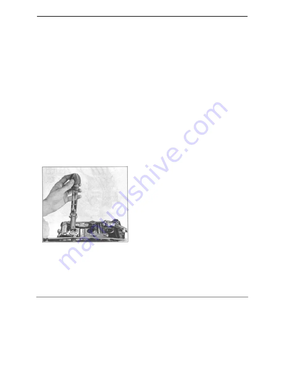
BATTERY SPECIFIC GRAVITY
Check the battery specific gravity with a hy-
drometer. A battery when fully charged should
read 1.270 specific gravity at 70° F. A uniform
hydrometer reading below 1.225 at 70° F. indi-
cates a low battery that should be recharged.
FIGURE 3
BATTERY LOAD TEST
Battery may be tested under load by connect-
ing a voltmeter across the terminals and cranking
the engine. Battery is satisfactory if
it will crank the engine for 1/2 minute and the
voltage does not drop below 4-1/2 volts. Slow
cranking speed or lower voltage may be due to
high resistance in the starter circuit. Check cables
and retest. (DO NOT crank for more than 1/2
minute at a time.)
A standard cell tester may be used to make the
load test. The cell tester has a shunt across the
terminals which places each cell under load. Each
cell should show 1-1/2 volts or over, and the vari-
ation between cells should not exceed .15 volts.
If a Starter-Battery Tester is not available, a
voltmeter can be connected across the battery ter-
minals while cranking t he engine with the starting
motor. The battery is in good condition if the
starter cranks the engine at a good speed for 1/2
minute and the voltage does not fall below 4-1/2
volts. DO NOT crank for more than 30 seconds
without allowing starter motor to cool.
NOTE: A slow cranking speed or voltage lower
than 4-1/2 volts indicates a weak cell or high
resistance in the connections to the starter.
Check battery cables and connections and re-
peat the "Load Test".
DISTRIBUTOR
1. Remove wires from cap anu inspect cap and
rotor for cracks and burned or corroded contacts.
Replace defective parts.
2. Clean spark plug cable sockets with tool No.
KMO-230.
CONTACT POINTS
1. Inspect distributor contact points f o r alignment,
corrosion, burning o r pitting and clean with
carbon tetracholoride.
2. Replace burned or corroded points. If points are
badly pitted, check condenser for over or under
capacity.
3. With a feeler gauge set the points for the proper
gap. Correct gap is .020".
NOTE: Contact points adjustment is made by
loosening the clamp screw (B) Figure 4, holding
11 ENGINE TUNE-UP
Содержание 1953 Super Jet
Страница 1: ......
Страница 2: ......
Страница 6: ...1 LUBRICATION...
Страница 7: ...LUBRICATION 2...
Страница 8: ...3 LUBRICATION...
Страница 31: ...ENGINE 26 FIGURE 4...
Страница 74: ...69 ELECTRICAL SYSTEM...
Страница 75: ...ELECTRICAL SYSTEM 70...
Страница 78: ...73 CLUTCH...
Страница 80: ...75 CLUTCH...
Страница 86: ...81 TRANSMISSION...
Страница 95: ...TRANSMISSION 90...
Страница 98: ...93 OVERDRIVE FIGURE 2...
Страница 112: ...107 OVERDRIVE Figure 1...
Страница 122: ...117 FRONT SUSPENSION...
Страница 130: ...125 STEERINGGEAR...
Страница 154: ...REFERENCE Source of Information Date Subject...
Страница 155: ......
Страница 156: ......


