


212
Series Tooling Alcoa Fastening Systems
19
See applicable illustrations.
Clean all components with mineral spirits, and
inspect for wear or damage. Replace as neces-
sary.
Always replace all seals and back-up
rings on/in disassembled components.
Use
O-rings, QUAD rings and back-up rings supplied
in Service Kit, 212KlT - - see
NOTES
. Smear
LUBRIPLATE 13OAA or PARKER-O-LUBE on
seals.
1. If bushings are being replaced:
Note:
Use LOCTITE 609, (Huck 503377) on
bushings when pressing into cylinder.
Use an arbor press. Place chamfered end of
Upper Bushing (58) in top of Cylinder (24).
Carefully press bushing squarely into cylinder.
Repeat procedure for Lower Bushing (59).
2. After new bushings are installed they may
have to be reamed, lapped, and honed to
bring their inside diameters to size for correct
fit and alignment with throttle valve.
3. Position Cable Assembly (21) in Trigger (20)
slot and push Linkage Pin (19) through holes
in trigger and cable assembly. Position
assembled trigger in Handle (3) and push
Slotted Pin (18) through holes in handle and
trigger.
4. Hold Head/handle (3) securely with lower end
pointing up. Turn Cylinder (24) bottom up, and
line up cylinder pin with handle hole. Press
Handle onto cylinder.
5. Assemble Gland Assembly - - see
FIGURE
12
Note:
Cup of POLY-SEAL (32) must face
toward top of tool when installed in Gland
(29).
Use new replacement POLY-SEAL (32),
Spacer and SPIRO-LOX Retaining Ring (34).
6.
CAUTION: DO NOT install Throttle Arm
Pivot Shoulder Screw (23) before Gland
(29) is installed to avoid damage to these
parts.
Apply VIBRATITE (Huck 505125) to threads
of Gland Assembly (29) - - follow directions on
container. Screw gland into head/handle.
Using 1 3/8 socket wrench, tighten gland to
90 ft. lbs. + 10 lbs.
7. Push Bumper (38) firmly over Gland (29) - -
face of bumper with two slots must face
toward bottom of tool.
8. Carefully press assembled Piston (39). Rod
(41). Nut (42), and QUAD Ring (40) into
Cylinder/handle (3) through Gland Assembly,
116134.
9. Push Cylinder Head (39) squarely into
head/handle taking care not to damage O-ring
(44). Install Retaining Ring (45).
10. Position O-ring (46) and Muffler (47) on center
of Cylinder Head (43). Position Gasket (48)
on cylinder and Spring (28) in lower bushing.
11. Carefully position Muffler End Cap (50) on
cylinder - - be certain that muffler is properly
positioned in recess of muffler end cap.
12. Hold end cap down and screw in three
Button Head Screws (51) and tighten with 1/8
hex key.
13. Place tool upright on level surface. Push
Throttle Valve (52) into cylinder.
14. Place ball end of Throttle Cable (21) in end of
Throttle Arm (22).
15. Slide throttle arm into slot on Throttle Valve
(52).
A
SSEMBLY
Содержание ALCOA 212
Страница 1: ...11 09 2009 HK838 INSTRUCTION MANUAL 212 PNEUDRAULIC INSTALLATION TOOL...
Страница 2: ......
Страница 4: ...This page is intentionally blank...
Страница 8: ...212 Series Tooling Alcoa Fastening Systems 6 Fig 1 Outline Drawing...
Страница 23: ...212 Series Tooling Alcoa Fastening Systems 21 Fig 5 Handle Assembly...
Страница 25: ...212 Series Tooling Alcoa Fastening Systems 23 Fig 10 Piston and Gland Removal...
Страница 26: ...212 Series Tooling Alcoa Fastening Systems 24 Fig 11 Piston and Gland Insertion assembly...
Страница 27: ...212 Series Tooling Alcoa Fastening Systems 25 Fig 12 Gland Assembly...
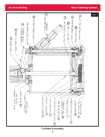
Страница 28: ...212 Series Tooling Alcoa Fastening Systems 26 Fig 13 Cylinder Assembly...