


212
Series Tooling Alcoa Fastening Systems
15
Fig. 4.1
Fig. 4
To measure stroke of tool with stall-
nut threaded onto piston:
1. Disconnect tool from airline -- remove nose
from tool.
2
With piston fully forward (end of RETURN
stroke), bottom the stall-nut on piston. Back
stall-nut off five (5) turns.
3. Cycle tool and hold trigger depressed - -
this keeps piston fully to the rear and at end
of PULL stroke. Thread stall-nut back onto
piston until it contacts stop.
4. Release trigger. Stall-nut wilI move forward
with piston. See
FIGURE 4
and measure “X”
dimension. This is the tools stroke.
5. If stroke is less than .812, refer to appropri-
ate previous section. Follow filling and top-
ping off instructions
To measure stroke of tool without
stall-nut:
1. Disconnect tool from airline - - remove nose
from tool.
2. With piston fully forward (end of RETURN
stroke), measure and record “X” dimension - -
see
FIGURE 4.1
.
3. Hold trigger depressed. Piston is now fully to
the rear and at end of PULL stroke. Measure
and record “Y” dimension.
4. Subtract “X” dimension from “Y” dimension.
5. If stroke is less than .812, refer to appropriate
previous section. Follow filling and topping off
instructions.
H
OW TO MEASURE STROKE
Содержание ALCOA 212
Страница 1: ...11 09 2009 HK838 INSTRUCTION MANUAL 212 PNEUDRAULIC INSTALLATION TOOL...
Страница 2: ......
Страница 4: ...This page is intentionally blank...
Страница 8: ...212 Series Tooling Alcoa Fastening Systems 6 Fig 1 Outline Drawing...
Страница 23: ...212 Series Tooling Alcoa Fastening Systems 21 Fig 5 Handle Assembly...
Страница 25: ...212 Series Tooling Alcoa Fastening Systems 23 Fig 10 Piston and Gland Removal...
Страница 26: ...212 Series Tooling Alcoa Fastening Systems 24 Fig 11 Piston and Gland Insertion assembly...
Страница 27: ...212 Series Tooling Alcoa Fastening Systems 25 Fig 12 Gland Assembly...
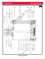
Страница 28: ...212 Series Tooling Alcoa Fastening Systems 26 Fig 13 Cylinder Assembly...