background image

Translation of the original operating and assembly instructions

Issue: 29.05.2020

ID 76644

English

Operating and assembly instructions

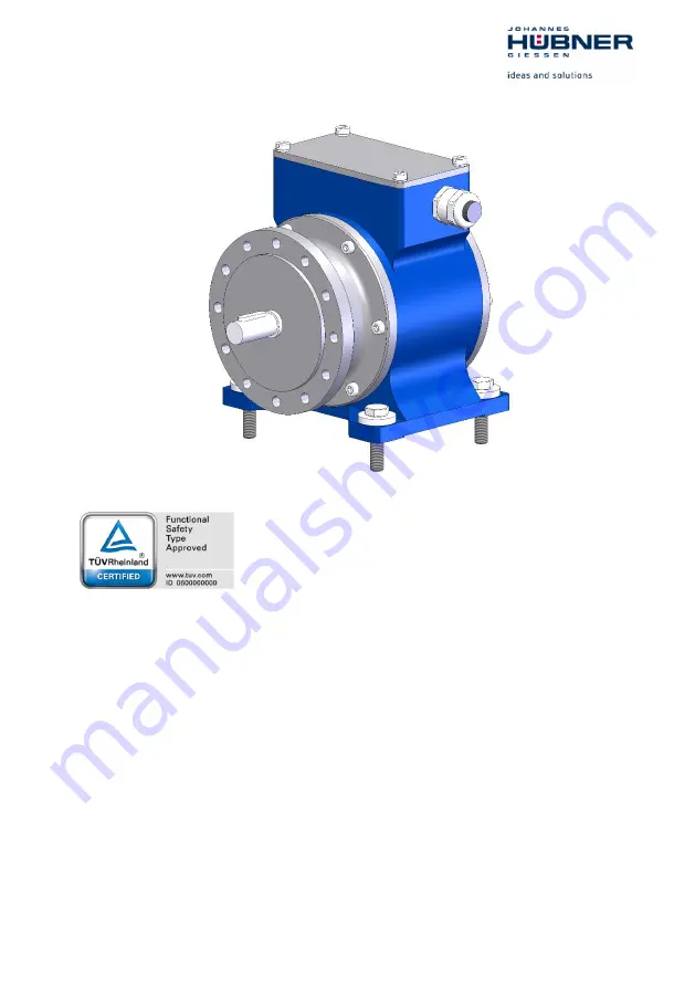
Incremental encoder with functional safety

FG 41 in solid shaft design

certified according to   EN 61508 part 1-7:2010 / IEC 62061:2015 SIL CL2 and

EN ISO 13849-1: PL d

and according to

EN 61508 Part 1-7:2010 / IEC62061:2015 SIL CL3 and
EN ISO 13849-1: PL e

Read the operating and assembly instructions prior to
assembly, starting installation and handling!
Keep for future reference!

Содержание FG 41

Страница 1: ...with functional safety FG 41 in solid shaft design certified according to EN 61508 part 1 7 2010 IEC 62061 2015 SIL CL2 and EN ISO 13849 1 PL d and according to EN 61508 Part 1 7 2010 IEC62061 2015 SI...

Страница 2: ...elektrischer Maschinen GmbH Fax 49 641 73645 Siemensstr 7 Internet www huebner giessen com 35394 Giessen Germany E mail info huebner giessen com Further current information on this product series can...

Страница 3: ...ngs graphics and other representations are protected by copyright and are subject to commercial property rights Duplications of any kind that are not combined with use of the machine are prohibited wi...

Страница 4: ...formation 15 3 Transport packaging and storage 16 3 1 Safety instructions for transport 16 3 2 Incoming goods inspection 16 3 3 Packaging disposal 16 3 4 Storage of packages devices 17 4 Technical Dat...

Страница 5: ...37 7 Incremental interface 37 7 1 Variant 1 analog incremental signals SIN COS 38 7 2 Variant 2 square wave incremental signals TTL HTL 39 8 Connection diagram 40 9 Replacing the Measuring System 41...

Страница 6: ...e distinguished in the chapter Main features on page 7 The products are labelled with affixed nameplates and are components of a system The following documentation therefore also applies operator s op...

Страница 7: ...SIL of a safety related system the lower the probability that the system cannot execute the required safety functions SIS Safety Instrumented System is used to protect a dangerous process and reduce...

Страница 8: ...Acceleration SLA Safe Acceleration Range SAR Safely Limited Position SLP Safely Limited Increment SLI Safe Cam SCA The measuring system as a sensor is always part of a safety chain The following shaft...

Страница 9: ...ternal signal monitor constantly checks the annulus relationship SIN x 2 COS x 2 1 Safety relevant errors are indicated by switching of the signal outputs to tri state The K0 reference signals are not...

Страница 10: ...ons are not met WARNING Means that death or serious injury can occur if the required precautions are not met CAUTION Means that minor injuries can occur if the required precautions are not met NOTICE...

Страница 11: ...ieved The complete processing chain of the safety function must then satisfy the requirements of the applied safety standard The safety measuring system may only be used in safety applications in conj...

Страница 12: ...perform the following safety checks With regard to Single fault safety and Ideal error detection please see IFA directive GS IFA M21 NOTES To enable the correct measures to be taken in the case of an...

Страница 13: ...ds to the number of periods revolution 1024 2048 or 4096 For the safety functions SDI SS1 SS2 SOS SSR SSM an annulus monitoring with DC 90 is required For the SLS safety function a two channel evaluat...

Страница 14: ...rements must be observed and communicated The operator is obliged to inform personnel on special operating features and requirements Prior to commencing work personnel working with the measuring syste...

Страница 15: ...umstances The measuring system must be taken out of operation immediately Potential hazards resulting from interactions with other systems and equipment which are or will be installed in the vicinity...

Страница 16: ...contains an optical system Use only the original packaging Inappropriate packaging material may cause damage to the unit in transit Storage temperature 40 C 85 C Store in a dry place Safety instructio...

Страница 17: ...from moisture Protect against heat Protect packages from heat above 40 C and direct sunlight If you intend to store the device for a longer period of time 6 months we recommend you use protective pack...

Страница 18: ...2 6 57 10 9 1 h Notice Measuring system is used only in applications with high or continuous demand rate MTTFd high Variant 1 1558 a Variant 2 622 a 2 DCavg Medium 90 Internal process safety time Time...

Страница 19: ...age 12 30 V DC acc to IEC 60364 4 41 SELV PELV Reverse polarity protection Yes Short circuit protection Yes by internal 1 A safety fuse Overvoltage protection Yes up to 60 V DC Current consumption wit...

Страница 20: ...trical 90 Reference signals N N once per revolution Output level 1 Vss 0 2 V at 100 differential Output current 20 mA Output frequency 500 KHz Short circuit proof Yes Cable specification see page 34 V...

Страница 21: ...Transient emissions EN 61000 6 3 Working temperature 40 C 85 C Ambient temperature Ta solid shaft Ta 84 1 0 004 n in C n speed in rpm Storage temperature 40 C 85 C dry Relative air humidity EN 60068 3...

Страница 22: ...cy Hz no of pulses per rev 60 rpm Shaft load axial radial Max Load on the encoder shaft Fa axial 300 N Fr radial 300 N Bearing life time 3 9 1010 revolutions Permissible angular acceleration 104 rad s...

Страница 23: ...TTL S Sin Cos Signal output Basic version 0 90 each with inverted signals zero pulse not safety certified Shaft with feather solid shaft 14j6 mm Type plate The type plate is located on the outside of...

Страница 24: ...osening All screwed connections must be inspected once a year In case of applications with low operating temperatures increased values for the start up torque result This fact is to be considered when...

Страница 25: ...pter 4 3 Ambient conditions on page 21 only with screwed on mating connectors or blind plugs Deep groove ball bearings Incremental encoders FG 41 are fitted with maintenance free greased for life deep...

Страница 26: ...possible fit the intermediate flange 7 in a manner that ensures the screwed sealing plug 17 points downwards If possible fit the device in a manner that ensures the cable gland 20 points downwards Exc...

Страница 27: ...shaft of the FG 41 9 7 Fit the FG 41 12 into both the centering 8 and coupling hub 4 at the same time 8 Secure the FG 41 using at least 6 screws and washers 10 distributed evenly around the circumfer...

Страница 28: ...ing You must be able to mount the coupling 7 without force Angle misalignment and parallel displacement between the drive shaft 1 and the FG 41 4 encoder shaft are mounting errors and should be kept a...

Страница 29: ...Strength class Screw Tightening torque 200 244 N mm2 M6x35 12 9 10 Nm 245 379 N mm2 M6x30 12 9 10 Nm 380 N mm2 M6x25 12 9 10 Nm 330 459 N mm2 M8x40 12 9 26 Nm 460 N mm2 M8x35 12 9 26 Nm NOTES If the...

Страница 30: ...no potential equalization currents flow via the shield 4 Tighten the cable gland and blanking plugs using a spanner NOTES Prior to delivery cable glands and blanking plugs are tightened finger tight o...

Страница 31: ...em The shielding should be connected with low resistance to protective ground using large shield clips at both ends The shielding should be grounded in the switch cabinet only if the machine ground is...

Страница 32: ...ities or Avoid ground loops Connect all shields double sided Shielding must not be interrupted Twisted pair wires A A B B 6 3 2 Connection scheme 2 1x Ground connection connection possibilities or Avo...

Страница 33: ...Encoder FG 41 33 6 3 3 Connection scheme 3 1x Ground connection connection possibilities or Avoid ground loops Connect all shields double sided Shielding must not be interrupted Twisted pair wires A...

Страница 34: ...e cable cross section must be matched to the cable length SIN SIN Min 0 14 mm2 and shielded 0 25 mm2 recommended However to ensure the signal quality and to minimize possible environmental influences...

Страница 35: ...incremental signals depends on the output frequency the applied supply voltage and the ambient temperature of the measuring system see the following diagrams 6 6 1 Analog incremental signals SIN COS...

Страница 36: ...mental signals TTL HTL TTL Interface Fig 4 Maximum permissible cable length for TTL interface HTL Schnittstelle Fig 5 Maximum permissible cable length for HTL interface Cable length in m Output freque...

Страница 37: ...the subsequent electronics If the input voltage exceeds 30 V these voltages occur accordingly at the HTL outputs This can lead to damage of the output or input circuit of the downstream processing uni...

Страница 38: ...048 and 4096 periods revolution are supported Measuring the signals against 0 V gives the following signal curve Fig 6 Signal curve with clockwise direction of rotation looking at the flange connectio...

Страница 39: ...nt on the device variant Resolutions of 1024 2048 and 4096 pulses revolution are supported The output levels are also specified by the factory setting TTL output stages and HTL output stages are suppo...

Страница 40: ...40 Incremental Encoder FG 41 8 Connection diagram FG 41T Connection diagram PN 228 400a 12 pole round plug M23 FG 41K Connection diagram PN 228 410 Terminal box...

Страница 41: ...easuring system must be installed in accordance with the specifications and requirements in chapter Assembly on page 24 The new measuring system must be connected in accordance with the specifications...

Страница 42: ...ent of the installation requirements defined in the user manual Safe mechanical fixing of the measuring system and safe positive connection of the driving shaft with the measuring system Chapter 5 Ass...

Страница 43: ...tenance free However to guarantee safe and fault free operations we rec ommend that you carry out the following inspections of the measuring system and the mount ing on a regular basis Inspections mus...

Страница 44: ...page 2 if required Mating connector Mating connector BG 109647 12 2 Mounting kit friction enhancing shims Mounting kit friction enhancing shims order no ID 24806 for enhancing friction in screw connec...

Страница 45: ...ouplings meet the following requirements Description Value shock resistance DIN EN 60068 2 27 6 ms 100 g vibration resistance DIN EN 60068 2 6 8 7 2000 Hz 20 g torque 3 Nm Temperature range 25 85 C ma...

Страница 46: ...46 Incremental Encoder FG 41 13 Dimension drawings FG 41 construction type B5 FG 41 T 12 pole round plug M23 HM 19 M 114093...

Страница 47: ...Incremental Encoder FG 41 47 FG 41 K Terminal box HM 19 M 114100...

Страница 48: ...48 Incremental Encoder FG 41 FG 41 K Mounting Example with screw on flange and coupling HKS 522 HM 19 M 114343...

Страница 49: ...Incremental Encoder FG 41 49 FG 41 construction type B35 flange and foot FG 41 T 12 pole round plug M23 HM 19 M 113973...

Страница 50: ...50 Incremental Encoder FG 41 FG 41 K Terminal box HM 19 M 114101...

Страница 51: ...Incremental Encoder FG 41 51 FG 41 K Mounting Example construction type B35 and coupling HKDS 522 HM 19 M 114336...

Отзывы: