background image

[5]

MAX. POWERLOSS

The maximum power dissipation of the power semiconductors is displayed in %. At 100% 
the amplifier switches off. For short signals the maximum power dissipation can be 
significantly higher than the average power dissipation. The displayed values are rated with 
the heat sink temperature and therefore greater at higher temperatures.

[6]

MEAN POWERLOSS

The average power dissipation of the power semiconductors is displayed in %. It is a 
measure of the long-term warming of the amplifier. At 100% the amplifier switches off. For 
short signals the maximum power dissipation can be significantly higher than the average 
power dissipation. The displayed values are rated with the heat sink temperature and 
therefore greater at higher temperatures.

[7]

QUIT

Quits the application.

[8]

RESET INTERLOCK

Only possible if the interlock-mode latching is configured. After safety shutdown has taken 
place, the interlock function must be reset manually. The amplifier can now be switched on 
again (Amplifier On).

[9]

STATUS INDICATION 

Green, Ready:
Signals the operational readiness of the amplifier.
Red, short-circuit_current exceeded
The short-circuit current cut-off has been activated.
Red, C exceeded
The permissible positive transistor current has been exceeded
Red, Current – exceeded
The permissible negative transistor current has been exceeded
Red, Power Loss + exceeded
The permissible operating range of the positive side of the power semiconductors has been 
exceeded.
Red, Power Loss – exceeded
The permissible operating range of the negative side of the power semiconductors has 
been exceeded.
Red, Temperature exceeded
The permissible temperature of the heat sink has been exceeded.
Red, Transformer temperature exceeded
The permissible temperature of the power transformer has been exceeded.
Red, Hardware Error:
An amplifier error was detected.

[10] CONNECT

Selection and activation of the device interface.

A1230-02 

A1230-MultiChannel-Control Software

Page 15

Содержание A1230-02

Страница 1: ...Operating Manual A1230 02 4 Quadrant Voltage Amplifier 2 Channel DC 7 MHz 450 V µs 2x 185 W Source 2x 68 W Sink Revision 3 0 MA 12300100 03 ...

Страница 2: ...ts 9 4 A1230 MultiChannel Control Software 13 5 Notes on Operation 18 6 Integration into Automated Test Systems 22 7 Maintenance and Service 25 8 Decommissioning and Disposal 26 9 Warranty 26 10 Contact Information 27 11 Guidelines 27 12 Document History 28 A1230 02 ...

Страница 3: ...apter box to easily connect both channels in parallel if more current is required Operation with equal output signals is strictly required in this setup The device is equipped with a temperature controlled low noise fan It also features an over temperature protection A power loss calculation and an absolute current monitoring guarantee perfect short circuit and overload protection The operation is...

Страница 4: ...pplication software A1230 Multichannel Control Power cable USB cable BNC wire ca 8 cm for bridge operation 4 mm connector for bridge operation Adapter box for parallel operation BNC wire ca 18 cm for parallel operation BNC T piece adapter for parallel operation A1230 02 Introduction Page 4 ...

Страница 5: ... or serious injury Type and source of danger Indicates a potentially hazardous situation which if not avoided could result in minor or moderate injury or property damage Type and source of danger Indicates important information about the product or procedures that should be considered for the correct functioning of the device 2 1 2 Used Warning Symbols Warning about a dangerous voltage Warning abo...

Страница 6: ...sk of electric shock the device housing must be earthed and therefore always operate the device via the supplied three core power cable with protective conductor The mains cable may only be plugged into a grounded socket with a protective earth contact An interruption of the protective earth conductor inside or outside the device reduces the safety of the device and is prohibited Safety Regulation...

Страница 7: ... to be performed contact the manufacturer of the device 2 3 Intended Use 2 3 1 Hardware The device is intended exclusively for use as an LF power amplifier Typical applications are the operation as voltage amplifier on passive loads Active loads are only permitted under certain conditions in agreement with the manufacturer Operation on active loads Active loads are only permitted under certain con...

Страница 8: ...User Operation may only be performed by qualified persons Reading and understanding the operating instructions Never use the device without having read and understood the operating instructions Always contact the manufacturer if you have any questions Qualified persons within the meaning of the safety instructions in this manual are authorized persons for commissioning and operating systems in acc...

Страница 9: ...h on the rear side 2 SAFETY SHUTDOWN 1 2 2 mm jacks to connect the safety shutdowns of both channels If connected a safety shutdown on one channel triggers the safety shutdown on the other channel This shutdown is indispensable and is provided automatically if the adapter box for parallel operation is used Using the safety shutdown is recommended in series operation as well 3 OUT OUT 4 mm safety s...

Страница 10: ...Reference potential is connected to protective earth via 1 MΩ 9 IN 50 KΩ 50 Ω Signal input isolated BNC socket Reference potential is connected to protective earth via 1 MΩ 10 READY PROTECTION LED Green Lights up when the amplifier is ready for operation READY Red Signals the intervention of a protection mechanism Red LED lights up constantly Over temperature protection the device switches on auto...

Страница 11: ...C SOCKET Inverted preamp output for simple setup of bridge circuits 4 INTERLOCK 1 BNC socket with shorting plug Remote controlled safety shutdown turns off the amplifier via an external switch breaker normally closed contact If safety shutdown was triggered AMPLIFIER ON LED is OFF and READY LED is ON 5 INTERLOCK 2 BNC socket with shorting plug Remote controlled safety shutdown turns off the amplif...

Страница 12: ...iggered AMPLIFIER ON LED is OFF and READY LED is ON 6 COMPUTER USB USB socket for connecting to a computer emulated COM Port 7 COMPUTER LAN Ethernet socket RJ 45 for connecting to a computer A1230 02 Operating Elements Page 12 ...

Страница 13: ...drivers and required additional programs are installed within the framework of the installation routine and require administrative access rights The driver devices required for the device are tested and do not represent any security risk The possible security risks documented by your operating system due to non certified drivers can be ignored Continue to follow the instructions on the screen The ...

Страница 14: ...the aid of the configuration menu startup configuration The amplifier then starts after the repeated switching on with the adjusted options 2 DEVICE Show the connection status device name and used port if a connection was established 3 INFO Here you find information about your GUI software version as well as the amplifier firmware and the amplifier hardware 4 TEMPERATURE The heat sink temperature ...

Страница 15: ...utdown has taken place the interlock function must be reset manually The amplifier can now be switched on again Amplifier On 9 STATUS INDICATION Green Ready Signals the operational readiness of the amplifier Red short circuit_current exceeded The short circuit current cut off has been activated Red Current exceeded The permissible positive transistor current has been exceeded Red Current exceeded ...

Страница 16: ...al output of the amplifier can be turned on and off by clicking the appropriate box 4 3 1 Connect Menu The available amplifiers are listed with their corresponding port A connection is established after clicking on Select device and confirm here The device name can be freely changed by a double click on a list entry please note tool tip With the aid of Check Devices connected devices can be search...

Страница 17: ... the state of the 100 kΩ input 4 INTERLOCK Setting the interlock mode LATCHING After an interlock the interlock state must be reset by a remote command before the amplifier can be switched through again LIVE The amplifier can be switched through again immediately after the interlock state has ended OFF Interlock deactivated default 5 SAVE VALUES The configuration data is stored as initial values i...

Страница 18: ...ltage 45 V for low output voltages and high load currents In order to keep the power loss of the amplifier low the operating voltage should always be selected according to the load Example The load current IL should be 2 ADC Load 1 RL 25 For IL 2 ADC an output voltage UA 50 VDC is required UA IL RL The power loss PV at the power amplifier results from the voltage drop at the power stage multiplied...

Страница 19: ...s a fast broadband amplifier that can deliver fast pulses with very high currents Please remember that the wiring can contribute a significant proportion to the inductance of your load In critical cases you should draw a coaxial wiring into consideration The A1230 is stable at all complex loads Since the output impedance of the amplifier will get inductive at higher frequencies this may lead to a ...

Страница 20: ...put voltage of the amplifier is not sufficient or if you need even higher slew rate the amplifier channels can be placed in a bridged mode For this purpose the rear Bridge Out 1 output of the first channel is connected to the 100 kΩ input of the second channel Also on the front panel connect both minus out jacks via the supplied short cable A1230 02 Notes on Operation Page 20 ...

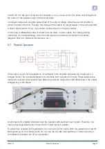
Страница 21: ...netic field coil ultrasonic transducers etc 5 7 Parallel Operation If the output current of the amplifier is not sufficient both amplifier channels can be placed in a bridged mode The provided adapter box combines both outputs via 50 mΩ These resistors are required to prevent unnecessarily high balancing currents caused by small differences in the output voltages e g a DC offset At all times both ...

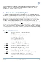
Страница 22: ...d out after execution of the command When an unknown command occurs the feedback is 0xFE and with a timeout 0xFD Several amplifiers can be driven via a COM interface In this case each amplifier requires its own address 1 99 default 1 which is determined by a command The address 100 is answered by all amplifiers regardless of the stored address 6 1 List of Remote Commands 0x01 Status query paramete...

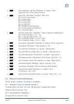
Страница 23: ...eters no answer 1 Byte address 0x14 Query amplifier type Parameters no answer 1 Byte type 0x10 0x15 Query firmware revision Parameters no answer 1 Byte revision 0x16 Set hardware revision Parameters 1 Byte revision e g 0x21 2 1 0x17 Query hardware revision Parameters no answer 1 Byte revision 0x53 Set Interlock Mode Parameter 1 Byte 0 Latching 1 Live 0x54 Set Interlock Parameter 1 Byte 0 Reset at ...

Страница 24: ...ameters use the manufacturer s interface listed below Current devices https www lantronix com products deviceinstaller Older devices https www eztcp com en download ezmanager php Drivers and product information on the currently used interfaces can be found at USB https www ftdichip com Drivers D2XX htm LAN https www lantronix com products xpico A1230 02 Integration into Automated Test Systems Page...

Страница 25: ...ry Shipping without a pallet usually leads to considerable transport damage the costs of which we do not cover Please include the RMA number with the delivery e g on the delivery note Ensure that the packaging is safe for transport the stresses during transport are enormous If possible use the original packaging when shipping the device Repairs will only be carried out by Dr Hubert GmbH External i...

Страница 26: ...ve product which was not damaged by negligence misuse improper installation accident or unauthorized repair or modification by the buyer This warranty is applicable only to defects due to material or workmanship Dr Hubert GmbH disclaim any other implied warranties of merchantability or fitness for a particular purpose Dr Hubert GmbH will not be liable for any indirect special incidental or consequ...

Страница 27: ...5 Bochum Germany Tel 49 234 970569 0 Fax 49 234 970569 29 service drhubert com www drhubert com 11 Guidelines This device complies with the relevant European Union harmonisation legislation EMC Directive Low Voltage Directive RoHS Directive A1230 02 Guidelines Page 27 ...

Страница 28: ...12 Document History Revision Date Changelog 2 0 March 2020 Backpanel and frontpanel images were updated 3 0 April 2021 New housing A1230 02 Document History Page 28 ...

Отзывы: