Hubbell Load:Logic Скачать руководство пользователя страница 4


  PD2795                                 02/2017 

                                                                                                                                  Page 3 

4. 

Switches

: Touch to display a list of switches found in the room.  Note that each switch display indicates the port number and 

switch’s address wheel setting (See RC Switch installation instructions for more details).  This is useful for distinguishing 
between switches of the same type in the room. 
 

There are a number of different switch types that might be discovered.  The setup screens for the various types will differ based on 
the function of the switch being selected. 
 
Touch a switch to see the current settings for that switch: 
 

A. 

Multifunction Switch

 - # series smart switch: 
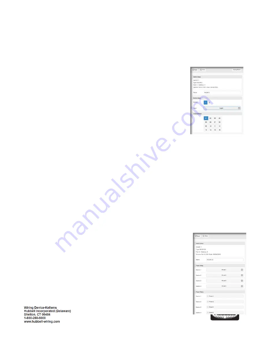
 

Name

: Allows the switch station to be given a meaningful name.  Use the keyboard to 

enter a name as desired.  
 

Button

: Blue background fill indicates the currently selected button. 


Type

: Indicates the current button type. The default button type is Toggle. Use the pull 

down to display a list of the available button types and select the desired Type from the 
list for this button: 


Toggle

: Touch ON/Touch OFF (default) 


ON

: Touch for ON only 


OFF

: Touch for OFF only 


Raise

: Ramp dimmer up 


Lower

: Ramp dimmer down 


Timed ON

: Touch for ON for set time period 


Disabled

: Button disabled 


Groups

: A blue background fill in one of the 16 available groups indicates that this switch is selected to be a member of 

this group number.  A gray background fill indicates that the switch is NOT a member of the group.  The switch may be a 
member of any or all groups if required. 
 

Make changes as needed.  Touch the <

Accep

t> button to save the changes or touch the <

Back

> button to exit WITHOUT saving 

the changes. 
 

B. 

ON/RAISE/LOWER/OFF (ORLO) and RAISE/LOWER (RL) Switches


Name

: Allows the switch station to be given a meaningful name.  Use the keyboard to enter a name as desired. 


Raise/Lower Setup

: Allows adjustment to the speed at which the dimming level will change as a Raise or Lower button 

held down. 
 

Rate

: Sets the rate at which level change messages are sent from the switch to the 

dimmer. Recommended setting is 300. 
 

% Change

: Sets the amount of change that occurs with each message.  A setting of 10 

will provide about a 5 second transition time from 0% to 100%. 
 

Groups

: A blue background fill in one of the 16 available groups indicates that this switch 

is selected to be a member of this group number.  A gray background fill indicates that the 
switch is NOT a member of the group.  The switch may be a member of any or all groups 
if required. 

 
Make changes as needed.  Touch the <

Accept

> button to save the changes or touch the <

Back

button to exit WITHOUT saving the changes. 

Содержание Load:Logic

Страница 1: ...unit For Indoor use only Do not use outdoors Disconnect switch or a circuit breaker must be provided and marked as the disconnecting device The use of accessory equipment not recommended by the manuf...

Страница 2: ...splayed These will include 1 Room Controllers Touch to display a list of room controllers found in the room Touch one of the room controllers to see a display showing controls for the relay s and dimm...

Страница 3: ...ion after an outage Last State is the default setting Touch Set Level to enter a specific dim level for power up Use the Level slider to set the desired level or touch the box to use the keyboard to e...

Страница 4: ...Groups A blue background fill in one of the 16 available groups indicates that this switch is selected to be a member of this group number A gray background fill indicates that the switch is NOT a me...

Страница 5: ...ne of the 16 available groups indicates that this sensor is selected to be a member of this group number A gray background fill indicates that the sensor is NOT a member of the group By default the oc...

Страница 6: ...urned OFF NOTE Make adjustments to the Design Level until the desired foot candle reading is achieved on the light meter at the task surface E Test Mode This is the factory default setting for Zone 1...

Страница 7: ...rcuit s it controls The MAC address will be needed later during the system setup process 3 Turn power OFF at the service panel 4 Mount the room controller s enclosure to a knockout opening of an elect...

Страница 8: ...Occupancy sensor with RP option 4 Loads NOTE Only one daylight sensor can be connected in each room zone Self Configuration The room controller s sequence of operation will automatically reconfigure...

Страница 9: ...s RCSNFx and RCSTOx RCSRLx RCSSCx RCSNRLFx will self configure by default to their respective descriptions For example RCSRLx is a Raise Lower dimmer Its default operation will be to change ALL the li...

Страница 10: ...2 Observe that the button is located slightly offset from the bezel opening The LED marked SVC will blink while the configuration button is being pressed 3 Release the configuration button and note t...

Страница 11: ...Simultaneously press and hold buttons A and B for three seconds until LED A begins to blink rapidly This indicates the room controller has transitioned from load configuration mode into photocell con...

Страница 12: ...n is complete the room controller will automatically exit configuration mode and return to normal operation Daylight harvesting will now be active based on the settings made during configuration Reset...

Отзывы: