Page 3 of 3
3940 Dr. Martin Luther King Drive
St. Louis, MO 63113
KIL00921465 FORM NO. K1465 06/15 ERO-8-029-15
Table A
Gland Size
Assembly
Torque (lbf-ft)
1/2”
20
3/4”
20
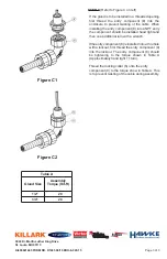
Figure C1
Figure C2
STEP C
(Refer to Figure C on left)
If the gland is to be installed in a threaded opening
first thread the entry component (8) into the
enclosure to prevent twisting of the cable. When
installing the entry component (8) into a NPT entry
the component should be installed hand tight and
then one additional turn with a wrench.
If the entry component (8) is installed into a thru hole
with a locknut, first thread the entry component (8)
into the locknut. The entry component (8) should
be tightening to the torque shown in Table A
(Approximately hand tight +1 turn).
Thread the locking collar (6) onto the entry
component (8) to the torque show in Table A. This
is to prevent twisting of the cable during assembly.


