background image

3

test results.

2. High voltage side: Connect with instrument terminal. The yellow, green, red and black

on the other end that correspond with A, B, C, O three bushings.

3. Low voltage side: Connect with instrument terminal. The yellow, green, red and black

on the other end that correspond with a, b, c,o three bushings.

4. AC 220V: the whole power input, then AC 220V frequency power supply.

5.

: Protective grounding column

6. Communication: serial communication

7. USB: U disk storage

8. Printer: Print the testing results after tested.

V.Instructions

(一)

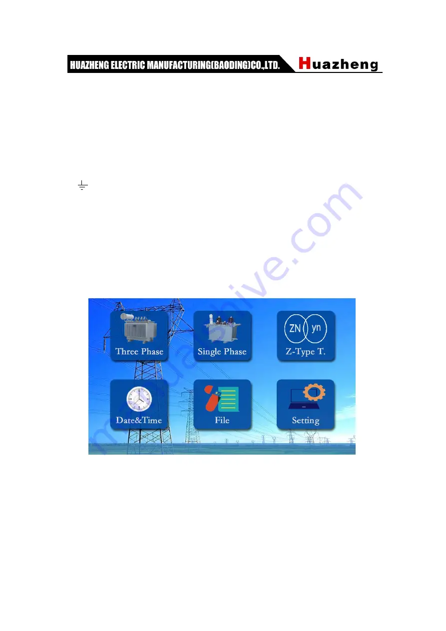
Menu description

Figure 1

After starting up the instrument, the startup interface is shown as figure 3. There are six

functional options in the startup interface, including: [three-phase measurement],

[single-phase measurement], [z-type transformer], [Scott transformer], [file recording] and

[system setting]. Click any function button to enter the setting.

(二)

Three-phase test interface

Содержание HZBB-10A

Страница 1: ...HZBB 10A Transformer Turns Ratio Tester Huazheng Electric Manufacturing Baoding Co Ltd...

Страница 2: ...al and operate and maintain the instrument according to the manual to prolong its service life Just a light press the test will be completed automatically is the operating characteristics of this inst...

Страница 3: ...d Characters 1 III Technical Index 2 IV Operating Panel Instructions 2 V Operating Instructions VI Connecting Method 3 VII Notice 9 VIII Instrument Common Problems And Inspection Methods 10 VIII After...

Страница 4: ...ement and the measurement is more accurate When the working power source is a generator there is no impact 2 Three phase output voltage is adopted to improve the test speed The angle between phases ca...

Страница 5: ...0000 Angle 0 360 2 Angle measurement 0 360 3 Accuracy 0 1 below500 0 2 501 2000 0 5 2001 10000 4 Output voltage automatically adjusted according to load 5 Resolution Minimum is 0 0001 Angle 0 01 6 Wor...

Страница 6: ...220V frequency power supply 5 Protective grounding column 6 Communication serial communication 7 USB U disk storage 8 Printer Print the testing results after tested V Instructions Menu description Fig...

Страница 7: ...e phase measurement z type transformer Scott transformer setting method are basically the same no longer repeat Test completion interface as shown below Figure 3 test completion interface 2 After the...

Страница 8: ...4 Click Time Setting to enter the time setting interface as shown in Figure 5 Figure 5 Click Year Month Day Hour Minute Second and the keyboard will pop up to set the time After entering the value cli...

Страница 9: ...Figure 7 Transformation ratio Click the transformation ratio button to switch to turns ratio data Previous Next You can view and print historical data Dump is to store the current data to the U disk P...

Страница 10: ...ord input and the user does not need to modify it Bluetooth Click Bluetooth to pop up the QR code as shown in Figure 9 scan the QR code with the corresponding software downloaded in the mobile phone t...

Страница 11: ...ing Object The Tester Idle Black 2 525 3 4 2 50 20 Single Phase Transformer and High Voltage connecting is according to the Diagram 2 as follows A O a b O Green Black Black Yellow Yellow Low Voltage H...

Страница 12: ...tapping the voltage combination of 110 8 1 25 10 0 transformers the rated tapping is 8 1 means 9 Enter the rated bit This gives an accurate measurement of the tapping position of the transformer whos...

Страница 13: ...sition and actual position inversion 8 Low voltage level of the transformer when the input voltage value is not enough the high and low voltage can be multiplied by 10 or 100 and so on 9 To test the S...

Страница 14: ...e side VIII After sale Service The product can be repaired free of charge or changed by a new one if it has quality problem for one year from sale We can provide reparation and technical services for...

Отзывы: