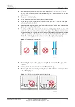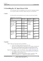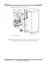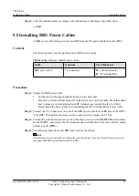
Step 4
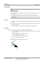
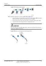
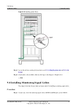
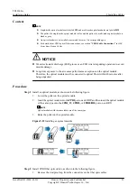
Label the installed cables according to the instructions in Attaching a Sign Plate Label.
----End
9.5 Installing BBU Power Cables
A BBU power cable feeds power into the BBU from the DC power distribution unit (PDU).
Context
The following table lists the specifications of BBU power cables.
Table 9-4
Specifications of BBU power cables
Cable
One End
The Other End
BBU power cable
3V3 connector
l
Cord end terminal
l
OT terminal (M4)
Procedure
Step 1
Prepare the BBU power cable.
1.
Cut the cable to the length suitable for the actual cable route.
2.
Prepare a cord end terminal and an OT terminal for one end of the cable. For details about
how to prepare cord end terminals and OT terminals, see Assembling the Cord End
Terminal and the Power Cable and Assembling the OT Terminal and the Power Cable.
Step 2
Connect the 3V3 connector at one end of the BBU power cable to the
-48V
port on the UPEU
in the BBU. Then tighten the screws on the connector with a torque of 0.25 N·m.
Step 3
Connect the cord end terminal at one end of the blue core wire to the
F13
BLVD
circuit breaker
for the DC PDU, and connect the OT terminal at one end of the black core wire to the DC output
positive bus bar (
RTN+
).
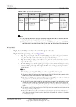
Step 4
The following figure shows the BBU power cable connections.
NOTE
If three BBUs or less are installed in a cabinet, the cord end termials at one end of the BBU power cables are
connected to
BLVD
circuit breakers from
F13
to
F15
.
TP48200A
Installation Guide
9 Installing Cables
Issue Draft B (2014-01-20)
Huawei Proprietary and Confidential
Copyright © Huawei Technologies Co., Ltd.
44

