TP482000B V300R002C03 Telecom Power
(TP482000B-N20B1, TP482000B-N20B2,
TP481200B-N20B1, and TP481200B-N20B2)
User Manual
7 Parts Replacement
Issue 07 (2020-04-10)
Copyright © Huawei Technologies Co., Ltd.
56
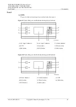
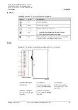
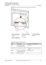
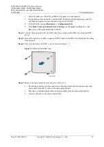
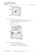
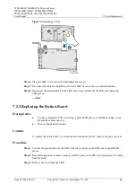
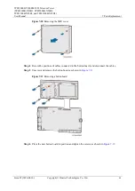
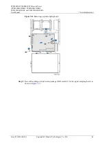
Figure 7-4
Removing the main control board
Step 6
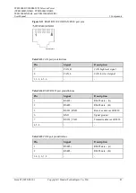
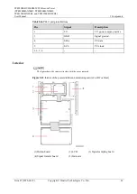
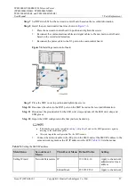
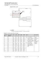
Record the settings of DIP switch S1 for the main control board, as shown in
Figure 7-5
DIP switch S1
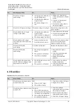
The DIP switch settings shown in
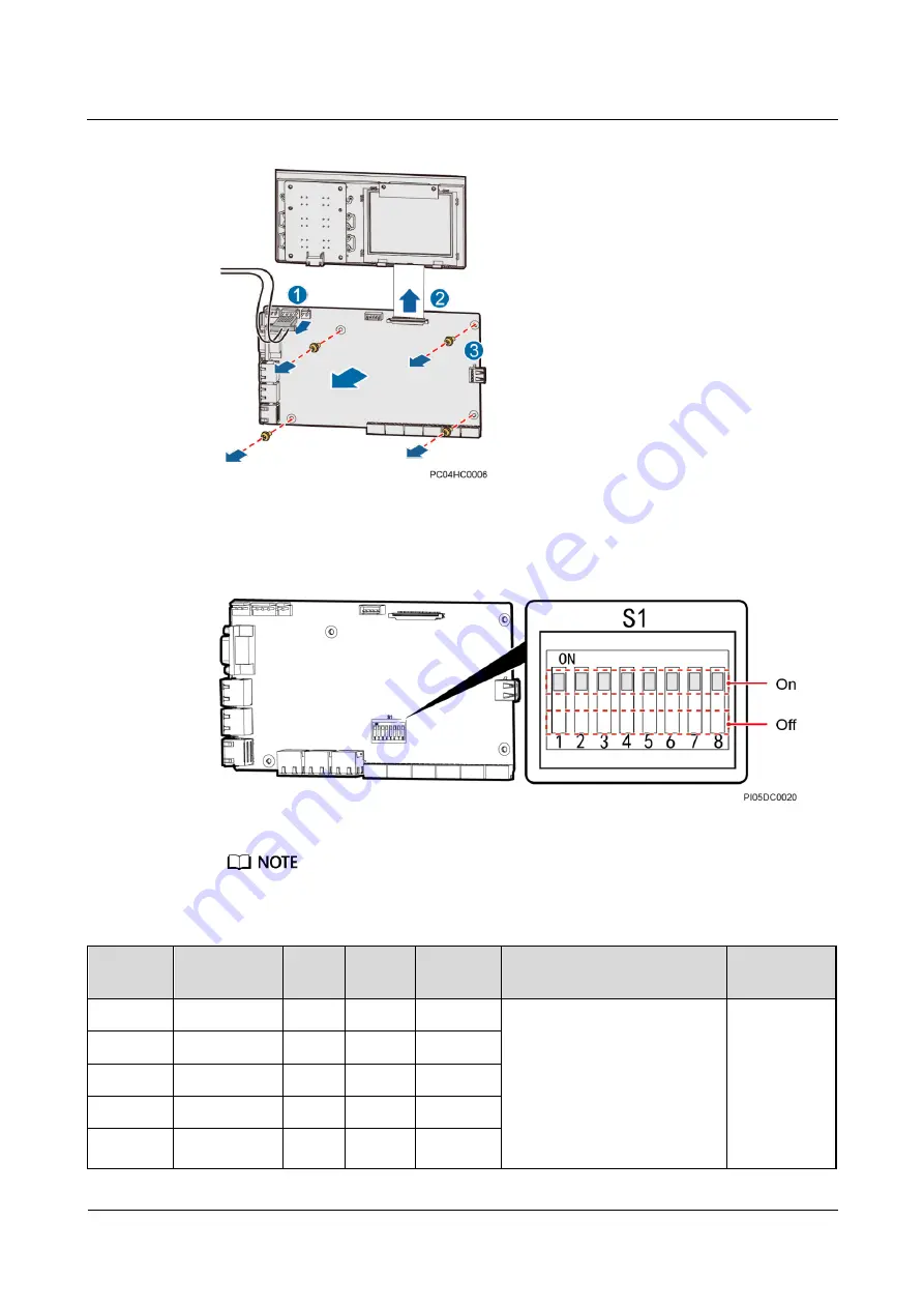
Table 7-1
Combined cabinet DIP switch settings
Cabinet
No.
Monitoring
Address
Bit 1
Bit 2
Bit 3
Bit 4
Bit 5–Bit 8
1
1
On
On
On
If a combined cabinet is
located at either end of the
power system, there is no
need to operate toggle switch
4.
If a combined cabinet is in
any other position, set toggle
switch 4 to Off.
Toggle
switches 5 to 8
are set before
delivery, and
no further
action is
required.
2
2
Off
On
On
3
3
On
Off
On
4
4
Off
Off
On
5
5
On
On
Off

