background image

TP482000B V300R002C03 Telecom Power 
(TP482000B-N20B1, TP482000B-N20B2, 
TP481200B-N20B1, and TP481200B-N20B2) 
User Manual 

6 Routine Maintenance 


Issue 07 (2020-04-10) 

Copyright © Huawei Technologies Co., Ltd. 

52 


No. 

Check Item 

If... 

Then... 

Check whether all cables are 
bound neatly. 

Cables are not properly bound. 

Bind cables neatly. 

Check whether the cabinet 
ground bar is securely connected 
to the site or equipment room 
ground point. 

The cabinet ground bar is not 
securely connected to the site or 
equipment room ground point. 

Connect the cabinet ground bar 
to the site or equipment room 
ground point. 

Check whether ground cables are 
rusty. 

Cables have corroded after 
being used for a long time. 

Replace rusty cables. 

Check whether the DC RTN+ 
busbar is grounded. 

The DC RTN+ busbar is not 
properly grounded. 

Connect the ground cable to the 
DC RTN+ busbar properly. 

Check whether cables are at 
danger of overheating 
deteriorating. 


Cables are too thin. 


Cables are not properly 
routed. 


Replace the cables with 
cables of the required 
thickness. 


Route the cables properly. 

Check whether cables are 
misshapen by metal parts. 

Cables are not properly 
installed. 

Replace the cables and route 
them properly. 

Check whether cables pass 
behind the air exhaust vents of 
rectifiers. 

Cables pass behind the air 
exhaust vents of rectifiers. 

Reroute the cables to prevent 
cable overheating. 

10 

Check whether power cables use 
standard terminals. 

Cables do not use stand 
terminals. 

Replace with standard terminals. 

11 

Check whether cable insulation is 
damaged. 

Cable insulation is damaged. 

Reinsulate the cables with 
insulation tape. 

Содержание TP481200B-N20B1

Страница 1: ...TP482000B V300R002C03 Telecom Power TP482000B N20B1 TP482000B N20B2 TP481200B N20B1 and TP481200B N20B2 User Manual Issue 07 Date 2020 04 10 HUAWEI TECHNOLOGIES CO LTD ...

Страница 2: ...tomer All or part of the products services and features described in this document may not be within the purchase scope or the usage scope Unless otherwise specified in the contract all statements information and recommendations in this document are provided AS IS without warranties guarantees or representations of any kind either express or implied The information in this document is subject to c...

Страница 3: ... this document are defined as follows Symbol Description Indicates a hazard with a high level of risk which if not avoided will result in death or serious injury Indicates a hazard with a medium level of risk which if not avoided could result in death or serious injury Indicates a hazard with a low level of risk which if not avoided could result in minor or moderate injury Indicates a potentially ...

Страница 4: ...nges made in earlier issues Issue 07 2020 04 10 Updated 7 2 1 Replacing the Main Control Board Issue 06 2019 12 01 Optimized the content about rectifiers Issue 05 2017 06 30 Modified 7 2 1 Replacing the Main Control Board Modified 7 3 1 Replacing the Signal Sampling Board Issue 04 2017 05 25 Optimized the descriptions Issue 03 2017 01 03 Modified 5 2 1 SMU05A Issue 02 2016 05 31 Modified Figure 4 ...

Страница 5: ...nical Safety 8 1 6 Battery Safety 11 2 Overview 15 2 1 Introduction 15 2 2 Features 16 3 Product Configurations 18 3 1 Single Cabinet Configurations 18 3 2 Typical Multi cabinet Configurations 21 3 3 Typical Multi cabinet Layout 22 4 Cabinet Configurations 23 4 1 Combined Cabinet 23 4 2 AC Cabinet 28 4 3 DC Cabinet 30 5 Components 34 5 1 Rectifier 34 5 2 Monitoring Unit 36 5 2 1 SMU05A 36 5 2 2 Po...

Страница 6: ... the Power Distribution Monitoring Unit 62 7 3 1 Replacing the Signal Sampling Board 62 7 3 2 Replacing the LCD 67 7 3 3 Replacing the Button Board 69 7 3 4 Replacing the Signal Transfer Board 71 7 4 Replacing an AC SPD 74 7 5 Replacing a Circuit Breaker 75 7 6 Replacing a Fuse 77 8 Emergency Handling 80 8 1 Background 80 8 2 AC Power Distribution Faults 80 8 3 AC Power Failure 80 8 4 DC Power Dis...

Страница 7: ...ge personal injuries or property damage are not covered under the warranty Follow local laws and regulations when installing operating or maintaining the equipment The safety instructions in this document are only supplements to local laws and regulations Huawei will not be liable for any consequences of the following circumstances Operation beyond the conditions specified in this document Install...

Страница 8: ... clothing helmet and shoes as shown in the following figure Use insulated tools or tools with insulated handles as shown in the following figure Follow the specified procedures for installation operation and maintenance Ensure that bolts are tightened with a torque wrench and marked using red or blue color Installation personnel mark tightened bolts in blue Quality inspection personnel confirm if ...

Страница 9: ...boards After installing the equipment remove idle packing materials such as cartons foam plastics and cable ties from the equipment area In the case of a fire immediately leave the building or the equipment area and turn on the fire alarm bell or make an emergency call Do not enter the building on fire in any case Do not stop using protective devices Pay attention to the warnings cautions and rela...

Страница 10: ...n ground terminal Indicates equipotential bonding This symbol is found with equipotential terminals inside equipment Indicates electrostatic discharge ESD This symbol is used in all electrostatic sensitive areas Before operating equipment in these areas wear ESD gloves or an ESD wrist strap Indicates that the equipment is safe to use at altitudes below 2000 m 6561 6 ft Indicates that the equipment...

Страница 11: ...ations of special equipment Professionals personnel who are trained or experienced in equipment operations and are clear of the sources and degree of various potential hazards in equipment installation operation and maintenance Trained personnel personnel who are technically trained have required experience are aware of possible hazards on themselves in certain operations and are able to take prot...

Страница 12: ...le is correct Before connecting the power supply ensure that cable connections are correct If the equipment has multiple inputs disconnect all the inputs before operating the equipment Cabling When routing cables ensure that a distance of at least 30 mm exists between the cables and heat generating components or areas This prevents damage to the insulation layer of the cables Do not route cables b...

Страница 13: ... a cabinet ensure that the cabinet is secured and will not tilt or fall down due to loss of balance which can cause personal injury or equipment damage Do not expose the equipment to flammable or explosive gas or smoke Do not perform any operation on the equipment in such environments Installation at Heights Working at heights refers to operations that are performed at least 2 meters above the gro...

Страница 14: ...ing working at heights Do not allow people to stay or pass under the area involving working at heights Inspect the scaffolding springboards and workbenches used for working at heights in advance to ensure that their structures are solid and not overloaded Dismantle the scaffolding from top down after finishing the job Do not dismantle the upper and lower layers at the same time When removing a par...

Страница 15: ...ladder is used ensure that the pull ropes are secured and the ladder is held firm Before using a ladder check that it is intact and confirm its load bearing capacity Do not overload it Ensure that the wider end of the ladder is at the bottom or protective measures have been taken at the bottom to prevent the ladder from sliding Ensure that the ladder is securely positioned The recommended angle fo...

Страница 16: ...egs of the ladder Drilling Holes When drilling holes into a wall or floor observe the following safety precautions Do not drill holes into the equipment Doing so may affect the electromagnetic shielding of the equipment and damage components or cables inside Metal shavings from drilling may short circuit boards inside the equipment Wear goggles and protective gloves when drilling holes When drilli...

Страница 17: ... do not disassemble alter or damage batteries for example insert sundries into batteries or immerse batteries in water or other liquids When replacing a battery use a battery of the same model or type Improper replacement may cause the battery to explode Do not connect a metal conductor to the battery poles or touch the battery terminals Otherwise the battery may be short circuited and heat up whi...

Страница 18: ...and secure batteries horizontally Note the polarities when installing batteries Do not short circuit the positive and negative poles of the same battery or battery string Otherwise the battery may be short circuited When installing a battery string retain at least one breakpoint to prevent a loop being formed After checking that the installation is correct close the breakpoints to finish the insta...

Страница 19: ...ly When moving or handling a battery whose electrolyte leaks note that the leaking electrolyte may hurt human bodies If the electrolyte overflows follow the instructions of the battery manufacturer or neutralize the electrolyte by using sodium bicarbonate NaHCO3 or sodium carbonate Na2CO3 Lithium Battery The safety precautions for lithium batteries are similar to those for lead acid batteries exce...

Страница 20: ...000B N20B1 TP482000B N20B2 TP481200B N20B1 and TP481200B N20B2 User Manual 1 Safety Precautions Issue 07 2020 04 10 Copyright Huawei Technologies Co Ltd 14 When maintenance is complete return the waste lithium battery to the maintenance office ...

Страница 21: ...400 A The TP482000B supports cabinet interconnection TP482000B cabinets of the same model can be interconnected and TP482000B cabinets can also be interconnected with TP483000D AC cabinets and DC cabinets Table 2 1 Product series Product Model Cabinet Type Remarks TP482000B TP482000B N20B1 2400 A combined cabinet Supports flexible power distribution TP482000B N20B2 TP481200B N20B1 1200 A combined ...

Страница 22: ...cy Rectifiers have a maximum efficiency of 98 and a power factor of 0 99 Automatic current equalization A digital current equalization technology is used to automatically equalize current among rectifiers without control from the SMU The current equalization imbalance is less than 5 Intelligent hibernation Rectifiers can hibernate automatically based on load power which saves energy reduces emissi...

Страница 23: ...on A built in DC surge protective device SPD provides 10 kV 8 20 µ s in differential mode and 20 kV 8 20 µ s in common mode A built in AC SPD provides 20 kA 8 20 µ s nominal lightning strike discharge current and 40 kA 8 20 µ s at the maximum Rectifiers provides 5 kA and 6 kV protection The signal ports resist 0 5 kV voltage to ground in differential mode and 1 kV in common mode High reliability T...

Страница 24: ...r 2 six 160 A NT00 fuses six 100 A NT00 fuses Layer 1 Six NT1 fuses six NT2 fuses six NT3 fuses Twenty four 63 A circuit breakers or sixteen 100 A circuit breakers Layer 2 Twelve NT00 fuses Twenty four 63 A circuit breakers or sixteen 100 A circuit breakers Rectifier circuit breaker Forty eight 1 pole 32 A circuit breakers Rectifier Forty eight R4850G2s R4850N2s or R4850S1s AC surge protection Two...

Страница 25: ...al blocks Load route Layer 1 six 500 A NT3 fuses Layer 2 six 160 A NT00 fuses six 100 A NT00 fuses Layer 1 Six NT1 fuses six NT2 fuses six NT3 fuses Twenty four 63 A circuit breakers or sixteen 100 A circuit breakers Layer 2 Twelve NT00 fuses Twenty four 63 A circuit breakers or sixteen 100 A circuit breakers Rectifier circuit breaker Sixteen 2 pole 63 A circuit breakers Rectifier Forty eight R485...

Страница 26: ...ixteen 100 A circuit breakers Rectifier circuit breaker Twenty four 1 pole 32 A circuit breakers Rectifier Twenty four R4850G2s R4850N2s or R4850S1s AC surge protection One 20 kA 40 kA SPD One 4 pole 32 A SPD circuit breaker Battery route Two 1000 A NT4 fuses Battery current monitoring Two 1000 A 25 mV shunts Total load current monitoring One 1000 A 25 mV shunt DC power indicator One DC power indi...

Страница 27: ...Twenty four R4850G2s R4850N2s or R4850S1s AC surge protection One 20 kA 40 kA SPD One 4 pole 32 A SPD circuit breaker Battery route Two 1000 A NT4 fuses Battery current monitoring Two 1000 A 25 mV shunts Total load current monitoring One 1000 A 25 mV shunt DC power indicator One DC power indicator green System alarm indicator One system alarm indicator red DC surge protection DC SPD 10 kA in diffe...

Страница 28: ...e PCS 2 3 4 5 Table 3 6 TP481200B N20B1 or TP481200B N20B2 typical configurations System Capacity kW 72 144 216 288 360 Combined cabinet TP481200B N20B1 or TP481200B N20B2 PCS 1 2 3 4 5 Connecting copper bar group 1 2 3 4 Inter cabinet signal cable PCS 2 3 4 5 TP483000D AC cabinets and DC cabinets can be connected to TP482000B cabinets 3 3 Typical Multi cabinet Layout Figure 3 1 360 kW 720 kW syst...

Страница 29: ...binet Configurations Issue 07 2020 04 10 Copyright Huawei Technologies Co Ltd 23 4 Cabinet Configurations 4 1 Combined Cabinet TP482000B N20B1 Figure 4 1 and Table 4 1 illustrate the TP482000B N20B1 configurations Load routes can be flexibly configured based on site requirements Figure 4 1 TP482000B N20B1 configurations ...

Страница 30: ...d in parallel Typical configuration 2 Load fuse Single layer six NT3 fuses Single layer twelve NT00 fuses 3 Space for rectifiers Forty eight 50 A rectifiers 4 Rectifier circuit breaker Dual layers forty eight 1 pole 32 A circuit breakers 5 AC SPD and SPD circuit breaker Two 20 kA 40 kA SPDs Two 4 pole 32 A SPD circuit breakers 6 SMU05A 1 PCS 7 Power distribution monitoring unit 1 PCS TP482000B N20...

Страница 31: ...ons No Name Specifications Remarks 1 Battery fuse Single layer two groups of two NT4 fuses connected in parallel Typical configuration 2 Load fuse Single layer six NT3 fuses Single layer twelve NT00 fuses 3 Space for rectifiers Forty eight 50 A rectifiers 4 Rectifier circuit breaker Dual layers sixteen 2 pole 63 A circuit breakers 5 AC SPD and SPD circuit breaker Two 20 kA 40 kA SPDs Two 4 pole 32...

Страница 32: ... on site requirements Figure 4 3 TP481200B N20B1 configurations Table 4 3 TP481200B N20B1 configurations No Name Specifications Remarks 1 AC input box One 3 pole 200 A circuit breaker Typical configuration 2 Cabinet ground bar 3 Load fuse Single layer four NT3 fuses two NT2 fuses Single layer twelve NT00 fuses 4 Space for rectifiers Twenty four 50 A rectifiers 5 Rectifier circuit breaker Single la...

Страница 33: ...opyright Huawei Technologies Co Ltd 27 No Name Specifications Remarks 7 Battery fuse Single layer two NT4 fuses 8 SMU05A 1 PCS 9 Power distribution monitoring unit 1 PCS TP481200B N20B2 Figure 4 4 and Table 4 4 illustrate the TP481200B N20B2 configurations Load routes can be flexibly configured based on site requirements Figure 4 4 TP481200B N20B2 configurations ...

Страница 34: ...use Single layer four NT3 fuses two NT2 fuses Single layer twelve NT00 fuses 4 Space for rectifiers Twenty four 50 A rectifiers 5 Rectifier circuit breaker Dual layers twenty four 2 pole 32 A circuit breakers 6 AC SPD and SPD circuit breaker One 20 kA 40 kA SPD One 4 pole 32 A SPD circuit breaker 7 Battery fuse Single layer two NT4 fuses 8 SMU05A 1 PCS 9 Power distribution monitoring unit 1 PCS 4 ...

Страница 35: ...on 2 MCCB TPA38401B N20B1 One 400 A MCCB Optional configuration TPA38631B N20B1 One 630 A MCCB Optional configuration 3 Manual transfer switch MTS TPA38401B N20B1 One 400 A MTS Optional configuration TPA38631B N20B1 One 630 A MTS Optional configuration 4 AC transfer switch ATS TPA38401B N20B1 One 400 A ATS Optional configuration TPA38631B N20B1 One 630 A ATS Optional configuration 5 Emergency ligh...

Страница 36: ...CB and three 1 pole 32 A MCBs Six 3 pole 160 A MCCBs Typical configuration TPA38401B N20B1 TPA38631B N20B1 MCB group 1 five 3 pole 63 A MCBs or three 3 pole 100 A MCBs MCCB four 100 A or 160 A 200 A or 250 A MCCBs up to a maximum of three layers MCB group 2 eight 3 pole 63 A MCBs or six 3 pole 100 A MCBs Optional configuration NOTE If you select three layers of MCCBs you do not need to select MCB ...

Страница 37: ... Battery route configurations for a DC cabinet No Item Cabinet Model Specifications Remarks 1 Battery fuse TPD48202B N20B1 TPD48302B N20B1 Two groups of two NT4 fuses connected in parallel Typical configuration 2 Contactor TPD48202B N20B1 TPD48302B N20B1 3000 A Optional configuration 3 Battery fuse TPD48202B N20B1 Six NT3 fuses Four NT4 fuses Optional configuration TPD48302B N20B1 4 Copper RTN exp...

Страница 38: ...PD48302B N20B1 Layer 1 eight NT3 fuses Layer 2 four NT2 fuses and four NT1 fuses Layer 3 fourteen NT00 fuses Typical configuration 2 Load fuse TPD48202B N20B1 TPD48302B N20B1 Single layer four NT4 fuses Optional configuration NOTE A maximum of three layers of fuses or circuit breakers can be configured for the load route If NT4 fuses are selected configure a maximum of two layers of fuses or circu...

Страница 39: ...r Manual 4 Cabinet Configurations Issue 07 2020 04 10 Copyright Huawei Technologies Co Ltd 33 No Item Cabinet Model Specifications Remarks breaker TPD48302B N20B1 6 63 A MCBs Single layer twenty five 1 pole 63 125 A MCBs The capacity of a single layer of load fuses or circuit breakers does not exceed 1000 A ...

Страница 40: ...Co Ltd 34 5 Components 5 1 Rectifier A rectifier converts AC input power into stable DC power Figure 5 1 Appearance 1 Power indicator 2 Alarm indicator 3 Fault indicator 4 Locking latch 5 Handle Table 5 1 Indicator description Indicator Color Status Description Power indicator Green Steady on The rectifier has an AC input Off The rectifier has no AC input The rectifier is faulty ...

Страница 41: ...w Off No alarm is generated Steady on A warning is generated due to ambient overtemperature The rectifier has generated a protection shutdown alarm due to ambient overtemperature or undertemperature AC input overvoltage or undervoltage protection has been triggered The rectifier is in hibernation state Blinking at 0 5 Hz The communication between the rectifier and the external device is interrupte...

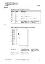
Страница 42: ...ns for setting and querying parameters on the LCD Table 5 2 Button description Button Name Description Up Scrolls through the menus or changes the value of a parameter Down Escape Displays software version information on the standby screen Returns to the previous menu without saving the settings OK Enters the main menu from the standby screen Enters a submenu from the main menu Saves parameter set...

Страница 43: ...er a menu is displayed the LCD screen becomes dark if no button is pressed within 30 seconds the standby screen is displayed if no button is pressed within 1 minute After login the login screen is displayed again if no button is pressed within 1 minute The preset password is 000001 To restart the SMU hold down and for more than 10 seconds To increase or decrease a parameter value quickly hold down...

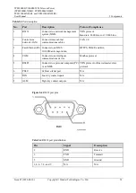
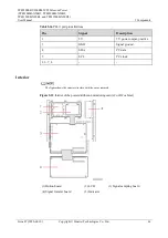
Страница 44: ...rea network CAN Connects inter cabinet communications cables CAN 2 0 3 Fast Ethernet FE Connects to an NMS 10 100M auto negotiation HTTPS SNMP and Bin 4 COM Connects to an intelligent communications device Modbus protocol 5 RS485 Connects to a personal computer PC or an NMS YDN protocol or Huawei master slave protocol 6 PELU Cabinet e label port N A 7 DIN Four dry contact inputs N A 8 ALM Eight dr...

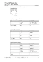
Страница 45: ... CAN port pin definition Pin Signal Description 7 CAN_H CAN high level signal 8 CAN_L CAN low level signal 1 2 3 4 5 and 6 N A N A Table 5 6 FE port pin definition Pin Signal Description 1 TX Transmit 2 TX 3 RX Receive 6 RX 4 5 7 and 8 N A N A Table 5 7 COM port pin definition Pin Signal Description 1 RS485 RS485 data 2 RS485 RS485 data 4 RS485 RS485 data 5 RS485 RS485 data 7 CAN_H CAN high level ...

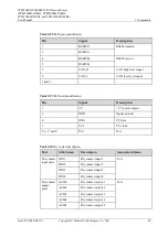
Страница 46: ... CAN low level signal 3 and 6 Table 5 9 PELU port pin definition Pin Signal Description 1 5 V 5 V power output 3 GND Signal ground 4 SDA I2 C data 5 SCL I2 C clock 2 6 7 and 8 N A N A Table 5 10 Dry contact description Port Silk Screen Description Associated Alarm Dry contact input ports DIN1 Dry contact input 1 N A DIN2 Dry contact input 2 DIN3 Dry contact input 3 DIN4 Dry contact input 4 Dry con...

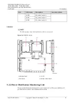
Страница 47: ... Alarm ALM6 Dry contact output 6 ALM7 Dry contact output 7 ALM8 Dry contact output 8 Interior The following figure shows the internal structure with the cover removed Figure 5 6 SMU05Ainterior 1 Button board 2 LCD 3 Indicator 4 Main control board 5 2 2 Power Distribution Monitoring Unit The power distribution monitoring unit is used to monitor AC or DC power distribution It provides detection alar...

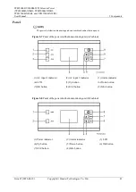
Страница 48: ...ring unit on a combined cabinet has no panel Figure 5 7 Panel of the power distribution monitoring unit AC cabinet 1 AC input 1 indicator 2 AC input 2 indicator 3 Alarm indicator 4 LCD 5 Up button 6 Down button 7 OK button 8 ESC button 9 Info button Figure 5 8 Panel of the power distribution monitoring unit DC cabinet 1 Power indicator 2 Alarm indicator 3 LCD 4 Up button 5 Down button 6 OK button ...

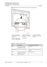
Страница 49: ...he upper level menu OK Enters the main menu from the standby screen Enters a submenu from the main menu Info Enters the standby screen from any screen or enters the active alarm screen from the standby screen Ports Figure 5 9 Ports on the power distribution monitoring unit AC or DC cabinet 1 RS485 RS232 port 2 COM port 3 CAN ports 4 PELU port 5 Ambient temperature sensor port AMBI_TEMP 6 Battery t...

Страница 50: ...t BAT_TEMP3 reserved 2 Battery temperature sensor port BAT_TEMP2 reserved 3 Battery temperature sensor port BAT_TEMP1 reserved 4 Ambient temperature sensor port AMBI_TEMP 5 CAN ports Table 5 12 Communications port description Port Description Communications Protocol CAN Connects inter cabinet communications cables CAN2 0 RS485 RS232 Connects to a host or NMS YDN protocol or Huawei master slave pro...

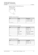
Страница 51: ... 13 CAN port pin definitions Pin Signal Description 7 CAN_H CAN high level signal 8 CAN_L CAN low level signal 1 2 3 4 5 6 Table 5 14 RS485 RS232 port pin definitions Pin Signal Description 1 RS485 RS485 data A 2 RS485 RS485 data B 3 RS232_RXD Receives data over RS232 6 GND Signal ground 7 RS232_TXD Transmits data over RS232 4 5 8 Table 5 15 COM port pin definitions Pin Signal Description 1 RS485 ...

Страница 52: ...46 Table 5 16 PELU port pin definitions Pin Signal Description 1 5V 5 V power output positive 3 GND Signal ground 4 SDA I2 C data 5 SCL I2 C clock 2 6 7 8 Interior The figure shows the interior structure with the cover removed Figure 5 12 Interior of the power distribution monitoring unit AC or DC cabinet 1 Button board 2 LCD 3 Signal sampling board 4 Signal transfer board 5 Indicator ...

Страница 53: ...000B N20B2 TP481200B N20B1 and TP481200B N20B2 User Manual 5 Components Issue 07 2020 04 10 Copyright Huawei Technologies Co Ltd 47 Figure 5 13 Interior of the power distribution monitoring unit combined cabinet 1 Signal transfer board 2 Signal sampling board ...

Страница 54: ...heck whether the cabinet door lock is damaged The door lock is rusty or has been tampered with Replace the door lock 4 Check whether the front and rear of rectifiers are blocked or dusty The front or rear of rectifiers is blocked or dusty Remove the blockage or clean up the dust 6 2 AC and DC Power Distribution Table 6 2 AC and DC power distribution maintenance No Maintenance Item If Then 1 Check ...

Страница 55: ... or short circuit Turn on the circuit breaker or replace the fuse 7 Check for DC busbar overvoltage A rectifier is abnormal Replace the abnormal rectifier 8 Check for DC busbar undervoltage The AC power supply has failed The system is overloaded A rectifier is abnormal 1 Resume the AC power supply 2 Check the load status and rectify faults if any 3 Replace the abnormal rectifier 9 Check whether th...

Страница 56: ...to an external DC power source that has a higher voltage 2 Check that the rectifier output voltage is normal 3 Replace the rectifier 6 4 SMU Table 6 4 SMU maintenance checklist No Check Item If Then 1 Check the green indicator status Off There is no DC input The SMU is faulty 1 Check that the DC input power cable is securely connected 2 Check that the communications cable is securely connected 3 R...

Страница 57: ...mp meter The current monitoring cable is loose The SMU is faulty 1 Check that the current monitoring cable is securely connected 2 Replace the SMU 5 Check whether the displayed battery charge current displayed on the SMU is the same as the actual current measured by a clamp meter The current monitoring cable is loose The SMU is faulty 1 Check that the current monitoring cable is securely connected...

Страница 58: ...y cables 6 Check whether the DC RTN busbar is grounded The DC RTN busbar is not properly grounded Connect the ground cable to the DC RTN busbar properly 7 Check whether cables are at danger of overheating deteriorating Cables are too thin Cables are not properly routed Replace the cables with cables of the required thickness Route the cables properly 8 Check whether cables are misshapen by metal p...

Страница 59: ...e power system is normal and batteries are in float charging mode Procedure Step 1 Put on protective gloves Step 2 Push the locking latch on the right of the rectifier panel upwards To prevent burns exercise caution when removing a rectifier because the rectifier may be hot as a result of continuous operation Step 3 Gently draw the handle outwards and then remove the rectifier from the slot as sho...

Страница 60: ...tained an ESD wrist strap a pair of ESD gloves an ESD box or bag a tool kit and the cabinet door key You have obtained a PC and network cable The computer supports Windows XP or later and Internet Explorer 7 0 or later The new SMU05A main control board is intact You have obtained the SMU05A IP address subnet mask gateway address and web user interface WebUI user name and password from the administ...

Страница 61: ...e displayed dialog box click Save to save the configuration file to the PC Step 2 Connect the ground cable for the ESD wrist strap and put on the ESD wrist strap and ESD gloves Step 3 Record the positions of cables connected to RJ45 ports on the SMU and disconnect the cables from the ports Step 4 Unscrew and remove the SMU cover as shown in Figure 7 3 Figure 7 3 Removing the SMU cover Step 5 Remov...

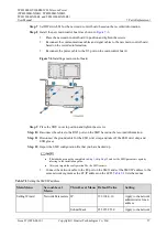
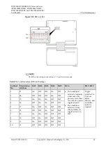
Страница 62: ...gure 7 5 DIP switch S1 The DIP switch settings shown in Figure 7 5 are for reference only Table 7 1 Combined cabinet DIPswitch settings Cabinet No Monitoring Address Bit 1 Bit 2 Bit 3 Bit 4 Bit 5 Bit 8 1 1 On On On If a combined cabinet is located at either end of the power system there is no need to operate toggle switch 4 If a combined cabinet is in any other position set toggle switch 4 to Off ...

Страница 63: ... and tighten the screws Step 10 Reconnect the cables to the RJ45 ports on the SMU based on the recorded information Step 11 Disconnect the ground cable for the ESD wrist strap and take off the ESD wrist strap and ESD gloves Step 12 Import the SMU configuration file that you have backed up If data backup cannot be completed in Step 1 skip Step 12 and set the SMU parameters again by referring to the...

Страница 64: ...word is Changeme 3 On the WebUI choose Maintenance Configuration File 4 Click Scan after Import Local Cabinet a new configuration file locate the configuration file on the PC and click Upload to import the file End 7 2 2 Replacing the LCD Prerequisites You have obtained an ESD wrist strap a pair of ESD gloves an ESD box or bag a tool kit and the cabinet door key The new LCD is intact Context To re...

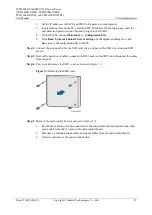
Страница 65: ...CD as shown in Figure 7 8 1 Disconnect the input power cable from the J12 port on the main control board 2 Disconnect the LCD flat cable from the main control board 3 Unscrew and remove the LCD Figure 7 8 Removing an LCD Step 5 Install the new LCD as shown in Figure 7 9 1 Place the new LCD in position and tighten the screws 2 Connect the LCD flat cable to the main control board 3 Reconnect the pow...

Страница 66: ...e ESD wrist strap and take off the ESD wrist strap and ESD gloves End 7 2 3 Replacing the Button Board Prerequisites You have obtained an ESD wrist strap a pair of ESD gloves an ESD box or bag a tool kit and the cabinet door key The new button board is intact Context To replace the button board you do not need to disconnect the AC input to the power system Procedure Step 1 Connect the ground cable...

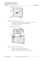
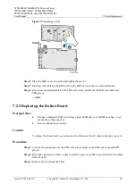
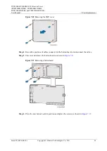
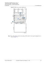
Страница 67: ...yright Huawei Technologies Co Ltd 61 Figure 7 10 Removing the SMU cover Step 4 Record the positions of cables connected to the button board and disconnect the cables Step 5 Unscrew and remove the button board as shown in Figure 7 11 Figure 7 11 Removing a button board Step 6 Place the new button board in position and tighten the screws as shown in Figure 7 12 ...

Страница 68: ...ews Step 9 Reconnect the cables to the RJ45 ports on the SMU based on the recorded information Step 10 Disconnect the ground cable for the ESD wrist strap and take off the ESD wrist strap and ESD gloves End 7 3 Replacing the Power Distribution Monitoring Unit 7 3 1 Replacing the Signal Sampling Board Prerequisites You have obtained an ESD wrist strap a pair of ESD gloves an ESD box or bag a tool k...

Страница 69: ...ribution monitoring unit and disconnect the cables from the ports Step 3 Unscrew and remove the cover from the power distribution monitoring unit as shown in Figure 7 13 Figure 7 13 Removing the cover from the power distribution monitoring unit Step 4 Remove the signal sampling board as shown in Figure 7 14 1 Record the positions of cables connected to the signal sampling board and disconnect the ...

Страница 70: ...20B1 and TP481200B N20B2 User Manual 7 Parts Replacement Issue 07 2020 04 10 Copyright Huawei Technologies Co Ltd 64 Figure 7 14 Removing a signal sampling board Step 5 Record the settings of dual in line package DIP switch S1 for the signal sampling board as shown in Figure 7 15 ...

Страница 71: ...Address Bit 1 Bit 2 Bit 3 Bit 4 Bit 5 Bit 6 Bit 7 Bit 8 1 23 On Off Off On Off If an combined cabinet is located at either end of the power system there is no need to operate toggle switch 6 If an combined cabinet is in any other position set toggle switch 6 to Off Toggle switches 7 to 8 are set before delivery and no further action is required 2 24 Off Off Off On Off 3 25 On On On Off Off 4 26 Of...

Страница 72: ...7 7 On Off Off On On 8 8 Off Off Off On On Table 7 5 DC cabinet DIPswitch settings Cabinet No Monitoring Address Bit 1 Bit 2 Bit 3 Bit 4 Bit 5 Bit 6 Bit 7 Bit 8 1 9 On On On Off On If a DC cabinet is located at either end of the power system there is no need to operate toggle switch 6 If a DC cabinet is in any other position set toggle switch 6 to Off Toggle switches 7 to 8 are set before delivery...

Страница 73: ...t the power cable to the J98 port on the signal sampling board Figure 7 16 Installing a signal sampling board Step 8 Place the cover on the power distribution monitoring unit and tighten the screws Step 9 Reconnect the cables to the RJ45 ports on the power distribution monitoring unit based on the recorded information Step 10 Disconnect the ground cable for the ESD wrist strap and take off the ESD...

Страница 74: ...Step 2 Record the positions of cables connected to RJ45 ports on the power distribution monitoring unit and disconnect the cables from the ports Step 3 Unscrew and remove the cover from the power distribution monitoring unit as shown in Figure 1 Step 4 Remove the LCD as shown in Figure 7 17 1 Disconnect the input power cable from the J98 port on the signal sampling board 2 Disconnect the LCD flat ...

Страница 75: ...ure 7 18 Installing an LCD Step 6 Place the cover on the power distribution monitoring unit and tighten the screws Step 7 Reconnect the cables to the RJ45 ports on the power distribution monitoring unit based on the recorded information Step 8 Disconnect the ground cable for the ESD wrist strap and take off the ESD wrist strap and ESD gloves End 7 3 3 Replacing the Button Board Prerequisites You h...

Страница 76: ...itoring unit and disconnect the cables from the ports Step 3 Remove the cover from the power distribution monitoring unit as shown in Figure 1 Step 4 Record the positions of cables connected to the button board and disconnect the cables Step 5 Unscrew and remove the button board as shown in Figure 7 19 Figure 7 19 Removing a button board Step 6 Place the new button board in position and tighten th...

Страница 77: ...signal transfer board is intact Context Disconnect the AC input to the power system only when you need to replace the signal transfer board for the power distribution monitoring unit in an AC cabinet Do not perform operations with power on because the signal transfer board for the power distribution monitoring unit in an AC cabinet has dangerous voltages Procedure Step 1 Connect the ground cable f...

Страница 78: ...nitoring unit is not connected to the AC cabinet skip Step 2 and Step 12 Step 3 Record the positions of cables connected to RJ45 ports on the power distribution monitoring unit and disconnect the cables from the ports Step 4 Unscrew and remove the cover from the power distribution monitoring unit as shown in Figure 1 Step 5 Unscrew and remove the cover from the signal transfer board as shown in Fi...

Страница 79: ...ment Issue 07 2020 04 10 Copyright Huawei Technologies Co Ltd 73 Figure 7 21 Removing the cover from a signal transfer board Step 6 Remove the signal transfer board as shown in Figure 7 22 1 Record the positions of cables connected to the signal transfer board and disconnect the cables 2 Unscrew and remove the signal transfer board ...

Страница 80: ...0 Place the cover on the power distribution monitoring unit and tighten the screws Step 11 Reconnect the cables to the RJ45 ports on the power distribution monitoring unit based on the recorded information Step 12 Loosen the screws on the maintenance terminal of the AC transformer in the AC cabinet move the metal bridgeware to the original position and tighten the screws Step 13 Disconnect the gro...

Страница 81: ...D gloves Step 2 Hold down the faulty AC SPD and pull it out as shown in Figure 7 23 Step 3 Install the new AC SPD as shown in Figure 7 23 Figure 7 23 Replacing anAC SPD Step 4 Disconnect the ground cable for the ESD wrist strap and take off the ESD wrist strap and ESD gloves End Follow up Procedure Check that the alarm for the AC SPD is cleared 7 5 Replacing a Circuit Breaker Prerequisites Before ...

Страница 82: ...r port of the circuit breaker using a Phillips screwdriver and open the buckle at the base of the circuit breaker using an insulated flat head screwdriver Step 5 Remove the circuit breaker from the guide rail Figure 7 24 shows how to remove the circuit breaker Figure 7 24 Removing the circuit breaker Step 6 Switch off the new circuit breaker Press the buckle at the circuit breaker base using an in...

Страница 83: ...ined the cabinet door key and tool kit The new fuse is intact and it is the same model as the old fuse Context Replacing an intact fuse will disconnect the power supply to loads Obtain the customer s consent before replacement If the fuse is in the battery route change the system output voltage to the same as the battery voltage Fuses are hot swappable You do not need to disconnect the AC input to...

Страница 84: ... fuse extracting unit upwards to lock the fuse 3 Hold the fuse extracting unit and pull out the fuse 4 Press the button on the fuse extracting unit 5 Move the fuse away from the fuse extracting unit Figure 7 27 Removing a fuse Step 3 Install the new fuse as shown in Figure 7 28 1 Insert the mounting ears of the new fuse into the two heads of the fuse extracting unit 2 Move the fuse to lock it into...

Страница 85: ...r TP482000B N20B1 TP482000B N20B2 TP481200B N20B1 and TP481200B N20B2 User Manual 7 Parts Replacement Issue 07 2020 04 10 Copyright Huawei Technologies Co Ltd 79 Figure 7 28 Installing a fuse Step 4 Tighten bolts to secure the fuse End ...

Страница 86: ...s is interrupted due to AC PDU faults connect AC input power cables to rectifier circuit breakers 8 3 AC Power Failure If an AC power failure will be rectified soon use batteries to power DC loads If an AC power failure will last a long time or is caused by unknown reasons start a diesel generator D G You are advised to keep the D G running for at least 5 minutes before switching the power system ...

Страница 87: ...ions equipment Countermeasures include Disconnect the AC supply Disconnect battery strings from the power system Use batteries or rectifiers to directly power the loads 8 5 Disasters Disasters include communications equipment failures caused by lightning strikes water damage earthquakes or fires Take precautions against disasters that could severely affect communications security and ensure that s...

Страница 88: ...4000 m the operating temperature decreases by 1 C for each additional 200 m Other requirements There should be no conductive dust corrosive gas or explosion hazard Dust corrosive substances pests molds and other indicators should be controlled in accordance with Class 3 1 requirements in ETSI EN 300 019 1 3 V2 3 2 or later AC input Input system TP482000B N20B1 220 380 V AC three phase four wire TP...

Страница 89: ...10 V AC AC input overvoltage protection threshold 305 V AC 10 V AC rectifier input voltage 5 V AC hysteresis 15 V AC AC input undervoltage protection threshold 85 V AC 3 V AC rectifier input voltage hysteresis 5 V AC max undervoltage protection recovery threshold 90 V AC 3 V AC DC output protection DC output overvoltage alarm threshold Default value 58 5 V DC 0 3 V DC DC output overvoltage alarm r...

Страница 90: ... lightning strike discharge current 20 kA 8 20 µ s maximum lightning strike discharge current 40 kA 8 20 µ s DC surge protection Differential mode 10 kA 8 20 µ s common mode 20 kA 8 20 µ s Safety compliance IEC EN60950 1 GB4943 Mean time between failures MTBF 500 000 hours 30 C Structure Power system dimensions H x W x D 2000 mm x 600 mm x 600 mm Weight 150 kg excluding rectifiers Protection level...

Страница 91: ...d be controlled in accordance with Class 3 1 requirements in ETSI EN 300 019 1 3 V2 3 2 or later AC input Input system 220 380 V AC three phase five wire Rated capacity TPA38401B N20B1 400 A TPA38631B N20B1 600 A Rated input line voltage 380 V AC Input voltage range 260 530 V AC line voltage Input frequency 45 66 Hz Cabinet structure Dimensions H x W x D 2000 mm x 600 mm x 600 mm Weight 120 kg Pro...

Страница 92: ... should be controlled in accordance with Class 3 1 requirements in ETSI EN 300 019 1 3 V2 3 2 or later DC output Rated voltage 53 5 V DC Nominal voltage 48 V DC DC output voltage 42 V DC to 58 V DC Maximum output current TPD48202B N20B1 2000 A load output 2000 A battery charge current 400 A TPD48302B N20B1 3000 A load output 3000 A battery charge current 500 A Regulated voltage precision 1 Voltage...

Страница 93: ...B1 TP482000B N20B2 TP481200B N20B1 and TP481200B N20B2 User Manual B Electrical Conceptual Diagram Issue 07 2020 04 10 Copyright Huawei Technologies Co Ltd 87 B Electrical Conceptual Diagram Figure B 1 Electrical conceptual diagram of TP482000B N20B1 ...

Страница 94: ...er TP482000B N20B1 TP482000B N20B2 TP481200B N20B1 and TP481200B N20B2 User Manual B Electrical Conceptual Diagram Issue 07 2020 04 10 Copyright Huawei Technologies Co Ltd 88 Figure B 2 Electrical conceptual diagram of TP482000B N20B2 ...

Страница 95: ...er TP482000B N20B1 TP482000B N20B2 TP481200B N20B1 and TP481200B N20B2 User Manual B Electrical Conceptual Diagram Issue 07 2020 04 10 Copyright Huawei Technologies Co Ltd 89 Figure B 3 Electrical conceptual diagram of TP481200B N20B1 ...

Страница 96: ...er TP482000B N20B1 TP482000B N20B2 TP481200B N20B1 and TP481200B N20B2 User Manual B Electrical Conceptual Diagram Issue 07 2020 04 10 Copyright Huawei Technologies Co Ltd 90 Figure B 4 Electrical conceptual diagram of TP481200B N20B2 ...

Страница 97: ...ower TP482000B N20B1 TP482000B N20B2 TP481200B N20B1 and TP481200B N20B2 User Manual B Electrical Conceptual Diagram Issue 07 2020 04 10 Copyright Huawei Technologies Co Ltd 91 Figure B 5 Electrical conceptual diagram of TP483000D AC ...

Страница 98: ...ower TP482000B N20B1 TP482000B N20B2 TP481200B N20B1 and TP481200B N20B2 User Manual B Electrical Conceptual Diagram Issue 07 2020 04 10 Copyright Huawei Technologies Co Ltd 92 Figure B 6 Electrical conceptual diagram of TP483000D DC ...

Страница 99: ...20B1 TP482000B N20B2 TP481200B N20B1 and TP481200B N20B2 User Manual C Engineering Design Drawings Issue 07 2020 04 10 Copyright Huawei Technologies Co Ltd 93 C Engineering Design Drawings Figure C 1 Engineering design drawing for the 1200 A cabinet ...

Страница 100: ...000B N20B1 TP482000B N20B2 TP481200B N20B1 and TP481200B N20B2 User Manual C Engineering Design Drawings Issue 07 2020 04 10 Copyright Huawei Technologies Co Ltd 94 Figure C 2 Engineering design drawing for the 2400 A cabinet fig1747175074710 ...

Страница 101: ...Result Measures 1 The cabinet paint does not flake and there are no scratches on the cabinet surface Passed Failed Repaint the cabinet Others________ 2 The cabinet is not rusted or corroded Passed Failed Improve the equipment room environment Others________ 3 The door lock is intact Passed Failed Replace the door lock Others________ 4 The front and rear of rectifiers are neither blocked nor dusty ...

Страница 102: ...he voltage data to the power supplier Others________ 5 The AC input voltage is not open phase Passed Failed Change the cables Provide the voltage data to the power supplier Others________ 6 The DC output circuit breaker is ON and the fuse is intact Passed Failed Rectify load faults Switch on the circuit breaker Replace the circuit breaker Replace the fuse Others________ 7 DC busbar overvoltage doe...

Страница 103: ...mmunications cables Replace the rectifier Others________ 3 The red indicator is off Steady on Off Troubleshoot the external DC power source Replace the rectifier Others________ Table D 5 SMU maintenance records No Maintenance Item Result Measures 1 The green indicator is steady on Steady on Off Change the DC input power cables Change the communications cables Replace the SMU Others________ 2 The r...

Страница 104: ...sor Replace the SMU Others________ 4 The total load current displayed on the SMU is the same as the actual current measured by a clamp meter Total load current ____ A Passed Failed Change the battery monitoring cables Replace the SMU Others________ 5 The battery charge current displayed on the SMU is the same as the actual current measured by a clamp meter Charge current ____ A Passed Failed Chang...

Страница 105: ...ected to the site or equipment room ground point Passed Failed Connect the cabinet ground cables Others________ 6 Ground cables are not rusty Passed Failed Change the rusty cables Others________ 7 The DC RTN busbar is grounded Passed Failed Modify the RTN busbar ground bar Others________ 8 Cables do not overheat or deteriorate Passed Failed Change the cables Others________ 9 Cables are squeezed an...

Страница 106: ...Huawei Technologies Co Ltd 100 E Acronyms and Abbreviations A ATS automatic transfer switch E EMC electromagnetic compatibility EMS electromagnetic susceptibility ESD electrostatic discharge F FE fast Ethernet H HTTPS hypertext transfer protocol secure L LCD liquid crystal display M MTS manual transfer switch S SMU site monitoring unit SNMP Simple Network Management Protocol ...

Страница 107: ...02C03 Telecom Power TP482000B N20B1 TP482000B N20B2 TP481200B N20B1 and TP481200B N20B2 User Manual E Acronyms and Abbreviations Issue 07 2020 04 10 Copyright Huawei Technologies Co Ltd 101 SPD surge protection device ...

Отзывы: